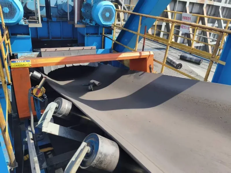
Quick Summary
Install a magnetic separator before the machine you need to protect, or after the last likely source of iron contamination when clean product is the goal. Choose a point where the target metal can reach the magnetic field and leave through a separate discharge or cleaning path.
When deciding where to install magnetic separator equipment, start with the job and then follow the material flow. Available floor space alone is a poor reason to choose a location.
| Your main goal | Where to start | What can change the choice |
|---|---|---|
| Protect a crusher, mill or shredder | Upstream of that machine, after the incoming iron enters the line | Buried iron, deep material, poor access or no reject outlet |
| Remove iron from finished product | After the last relevant contamination source, before packing or loadout | Further wear points or unprotected transfer equipment downstream |
| Recover a magnetic material | Where the target is sufficiently freed from other material and the feed is controlled | Particle size, magnetic response and whether the process is dry or wet |
Should the Separator Go Before or After Processing Equipment?
Put it before the equipment for damage prevention, and after a contamination-generating step for product cleaning. A line may need both positions because the two magnets solve different problems.
For machine protection: remove iron before it can cause damage
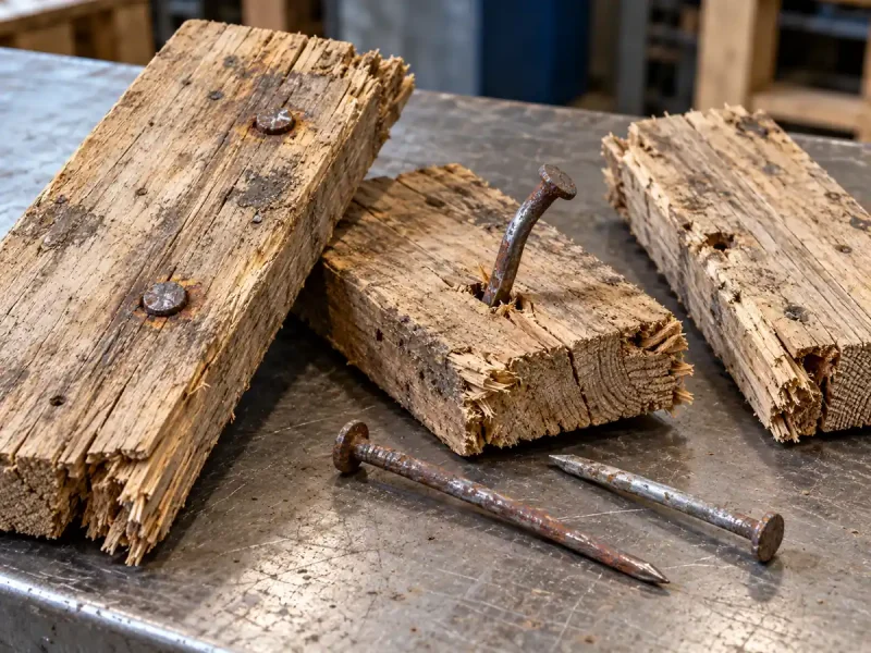
Unwanted iron and steel pieces are often called tramp iron. Follow their likely entry points from incoming material to the machine at risk. Choose a separation point between those two places.
A magnet after a crusher can remove steel from the crushed output. It cannot prevent that same piece from entering the crusher first. If incoming scrap can damage the crusher, provide removal before it; treat post-crushing recovery as a separate duty.
For product purity: catch contamination after the last wear source
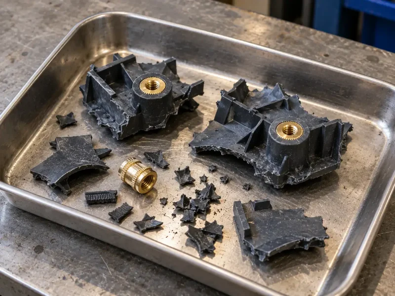
An early magnet does not catch iron introduced farther down the line. A screw conveyor, mixer or other wearing component after that magnet can add fresh contamination.
Consider a dry-powder line with receiving, mixing, screw transfer and packing. A receiving magnet addresses incoming iron. If screw wear is a relevant final-product risk, another capture point after the screw and before packing addresses that later source. Putting both magnets before the screw leaves that risk unresolved.
Puritan’s placement guidance separates receiving, equipment protection and final loadout. Bunting’s plastics-plant guide likewise uses several control points. The useful lesson is to map where metal can enter, rather than expecting one installation to cover the whole plant.
For mineral recovery: separate after enough liberation
For recovery, the magnetic mineral may first need to be freed from the surrounding rock. This is called liberation. Crushing, grinding or classification can therefore come before the recovery separator.
That does not remove the need for upstream tramp-iron protection. Draw the protection magnet and the mineral-recovery stage as two different jobs on the process sketch.
Where Should an Overband Magnet Sit on a Conveyor?
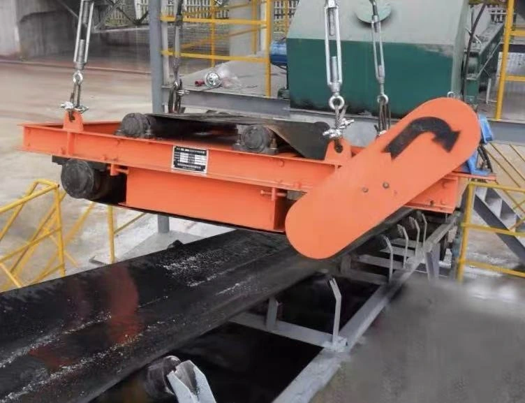
Compare a position near the head-end discharge with a crossbelt position above the carrying run. Favor the point that exposes the target iron while leaving a workable route for metal discharge and service.
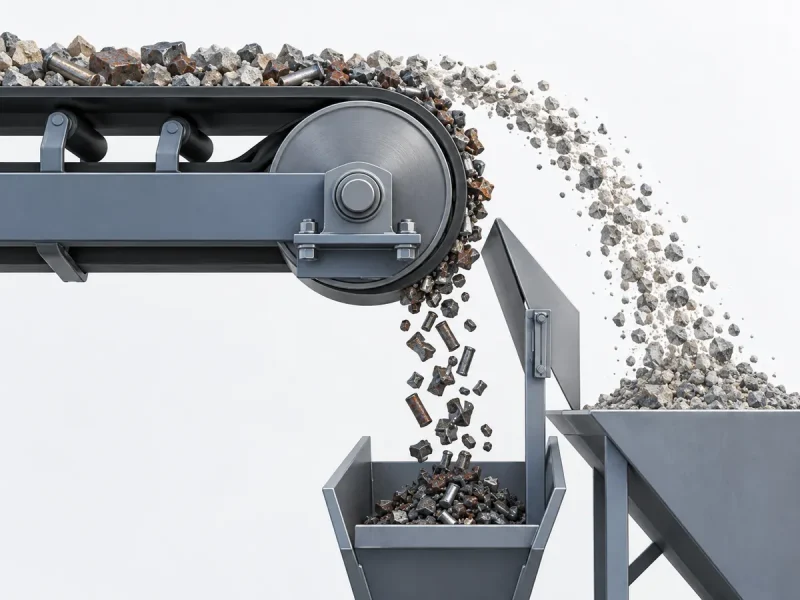
An overband magnet lifts responsive iron from the main material stream. Its moving cleaning belt carries that iron to a collection point. Inline and crossbelt describe the cleaning belt’s direction relative to the conveyor; head-end and carrying-run describe the location.
Compare the carrying run with the head-end discharge
| Arrangement | When to consider it | Main trade-off |
|---|---|---|
| Crossbelt above the carrying run | An existing conveyor has a suitable support point and side-discharge space. | The magnet must lift buried iron through the moving material layer. |
| Inline near the head-end discharge | The discharge trajectory is accessible and lengthwise space is available. | The magnet, splitter and collection route must fit the changing material path. |
| Crossbelt over the head pulley | Head-end exposure is useful and iron can discharge sideways. | Head-pulley construction, clearance and side collection need a coordinated layout. |
The Dings overhead-magnet selection guide illustrates all three arrangements. At discharge, material opens out and can free trapped iron, making capture easier than pulling through a compact burden. This benefit depends on the actual trajectory; it is not a reason to place every magnet at a transfer point.
Follow the iron all the way into its collection point
Trace the expected path from capture to release. Keep the reject chute and bin outside the clean-material path. Where the streams could cross, an adjustable splitter separates them. Include the largest expected iron piece when checking the opening.
If the only available side space is above another product conveyor, that is not yet a complete crossbelt installation. Reroute the reject, compare a feasible inline layout, or move the separation point.
Our overband magnetic separators can be reviewed for crossbelt or inline arrangements. We use belt speed, material depth, target iron and the available discharge space to narrow the layout.
Where Do Dry Drums and Pipeline Magnets Fit?
Place a dry drum at a controlled feed or transfer point with separate outlets. Place a suitable pipeline magnet where the full intended material stream passes through its capture area. Both need enough space for flow, cleaning and maintenance.
Dry drum: after controlled feeding, before the two outlets
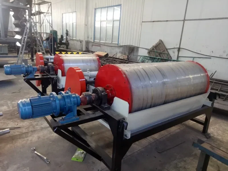
A dry drum magnetic separator needs material spread across its useful working width. A feeder or controlled chute helps avoid a deep heap at one end. Leave room below for magnetic and non-magnetic streams to stay apart.
Eriez’s dry-drum installation manual calls for controlled, uniform feed and an adjustable non-magnetic divider. It also warns against heavy pieces striking and damaging the shell. When adding a drum below a high drop, solve the feed impact and distribution before fixing the drum position.
During setup, observe where each stream falls and adjust the splitter through a safe, approved procedure. A divider that favors iron removal can also send more good material into the reject. Compare both outlets when judging the setting.
A magnetic head pulley is a different arrangement: it replaces the conveyor head pulley and retains responsive iron around the belt toward a separate underside discharge. A standalone drum requires its own feed and support layout.
Pipeline magnet: in the full flow, with room to clean
Our pipeline magnetic separator range on this site covers dry powders and granules in gravity chutes, spouts and enclosed transfer lines. Choose a point where the product passes through the intended magnetic passage without an uncontrolled bypass.
Match the internal passage and cleaning access, not only the inlet diameter. Powder can bridge around an obstruction, while sticky material can build up and change the flow. If a proposed point cannot feed consistently, improve the transition or choose another position before increasing magnetic strength.
Mark the full travel of the removable assembly or access door on the layout. An empty space beside the housing is useful only if it is large enough for the actual cleaning motion.
What Should You Measure Before Fixing the Position?
Measure the space needed for the material to pass and the distance to the hardest-to-reach target separately. A safe gap above the material does not tell you how far the magnet must reach into the load.
The depth of material on a conveyor is called burden depth. Iron near the belt can be much farther from an overhead magnet than iron on top. If the unit catches exposed pieces but misses buried ones, map those two distances before changing the magnet.
Use drawings or measurements taken with machinery safely stopped and isolated. Observe running material flow only from outside guarded areas.
- Draw the loaded cross-section. Show normal and maximum burden, the belt’s trough profile and the largest expected lumps. Include peaks rather than measuring an empty belt only.
- Mark the measurement reference. Distinguish the magnetic block face from the outer cleaning-belt surface. Use the selected unit’s drawing to identify what its suspension dimension means.
- Mark the farthest target position. Include iron near the bottom and edges of the stream. This is the distance relevant to capture, not just the free clearance above the product.
- Record flow and speed. For a conveyor, use the operating belt speed and normal/peak load. Near discharge, show the material trajectory. For a chute, show the opening, angle and any surges.
- Show nearby steel. Include idlers, head pulley, chute walls, beams and guards near the magnetic zone so their effect can be reviewed.
The Eriez TP manual defines its suspension reference and specifies non-magnetic components in relevant installation positions. Treat these as design details to resolve for the selected machine. Do not copy a height, clearance or idler requirement from a different model without reviewing its magnetic layout.
If extra headroom can only be gained by raising the magnet, compare the resulting capture distance before accepting the change. Reducing a feed surge, opening the material at another transfer point or changing the arrangement may solve both clearance and capture more effectively.
Can the Iron Be Discharged and the Magnet Be Serviced Safely?
A location is usable only when captured metal can be collected and the equipment can be cleaned, inspected and repaired safely. Include those tasks in the layout before the support steel is built.
- Reject handling: show the chute, bin, emptying route and access. A full bin or blocked outlet can make captured iron re-enter the product or accumulate around moving parts.
- Cleaning access: leave the complete pull-out or door-swing distance and a place for the operator to work. Include where collected sharp metal will be placed.
- Component service: reserve access to bearings, drives, guards and belt adjustment points. Check how a cleaning belt or heavy assembly will be removed.
- Support and lifting: have the support, suspension and lifting arrangement designed for the selected equipment and site loads. A beam that happens to be nearby is not a support design.
If manual cleaning would require repeated work from an awkward elevated position, compare a serviceable location or an appropriate automatic-cleaning design. Automatic discharge still needs inspection and repair access.
For hands-on measurement, adjustment or cleaning, stop and isolate the relevant machinery under the site’s safe procedure. A permanent magnet remains magnetic after its drive power is isolated. Keep loose ferrous tools under control and keep personnel clear of pinch and attraction hazards.
How Do You Check That the Installation Works?
Check capture, retention and discharge under representative material conditions. A successful installation removes the defined target at the required flow without unacceptable product loss, blockage or metal falling back into the clean stream.
Start with the agreed target: protection from specified tramp pieces, a residual-contamination limit, or recovery of a magnetic fraction. These call for different checks. A clean-looking reject bin alone cannot tell you whether the product meets its target.
- Record the installed geometry. With the equipment safely isolated, compare reference dimensions, splitter position and cleaning access with the accepted drawing.
- Complete mechanical commissioning. Qualified personnel check travel direction, belt tracking, guards, discharge clearance and the required stop or interlock functions.
- Run the agreed material trial. Use representative feed at normal and peak operating conditions. Record material size, moisture, rate, bed depth or trajectory, speed and separator settings.
- Compare the resulting streams. Use the agreed sample and measurement method to assess remaining contamination or recovery. For continuous separation, also measure good material lost with the magnetic fraction.
Any deliberate challenge with test metal needs a planned, contained procedure, accounted-for pieces and a safe collection method. Do not drop loose steel into a live production line as an improvised test.
| What you observe | Check first | What to change or test next |
|---|---|---|
| Exposed iron is caught; buried iron passes. | Deepest target distance and material depth. | Compare a thinner, more even feed or a more accessible capture point. |
| Iron is lifted but returns to the product. | Cleaning-belt travel, retention, splitter and reject clearance. | Correct the release path and repeat the capture-to-collection check. |
| The result worsens during feed surges. | Peak bed depth, speed and discharge trajectory. | Stabilize feeding or review the installation for the peak condition. |
Keep the baseline settings and result together. When performance changes, compare the same target and measurement method before deciding whether the position, feed or separator needs to change.
Choose the Point That Solves the Right Problem
The right magnetic separator location combines the correct place in the process with workable capture, discharge and service conditions. Protect a machine before the iron reaches it. Clean finished product after relevant downstream contamination sources. Give a recovery separator the feed condition its separation duty needs.
For a Corvelan installation review, send a process sketch showing the equipment immediately before and after the proposed point. Include the material, target metal, normal and peak throughput, available dimensions, and photos of the feed and discharge area. We can review the equipment family and layout details from those inputs.
Installation Questions
Can a magnetic head pulley and an overhead magnet share the same conveyor head?
Do not combine them at the same head position without a coordinated magnetic and mechanical design. One magnet can affect the other’s intended field and material path. The Eriez TP manual specifically warns against placing a magnetic head pulley below that suspended magnet. Review the selected equipment drawings together; adding a second magnet is not automatically an improvement.
Should a metal detector go before or after the magnet?
After the magnet can be useful when magnetic separation removes iron first and detection then targets remaining metal. The detector still needs enough downstream distance for the required stop or reject action before the protected point. Resolve interference and spacing from the two equipment designs rather than using one standard gap.
What if there is no space to pull out the cleaning assembly?
Change the location, access direction or cleaning design before installing it. A housing that fits between flanges may still be impossible to clean. Move it to a serviceable section of the line or compare a suitable automatic-cleaning unit, while retaining access for inspection and repair.
Can the same pipeline separator be used for pneumatic conveying or slurry?
Use a separator designed for that conveying method and material. Our linked pipeline range covers dry-bulk gravity lines. A pressurized pneumatic line, liquid or slurry needs matching flow passages, pressure construction, seals and cleaning arrangements. A matching pipe diameter alone does not establish suitability.
Does a good Gauss reading mean the location is correct?
No. A Gauss reading describes magnetic flux density at a defined measurement point. Installation performance also depends on the target’s distance, feed behavior and successful discharge. Compare the reading with its baseline method, then assess the actual material result at the required flow.