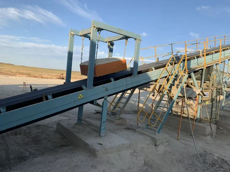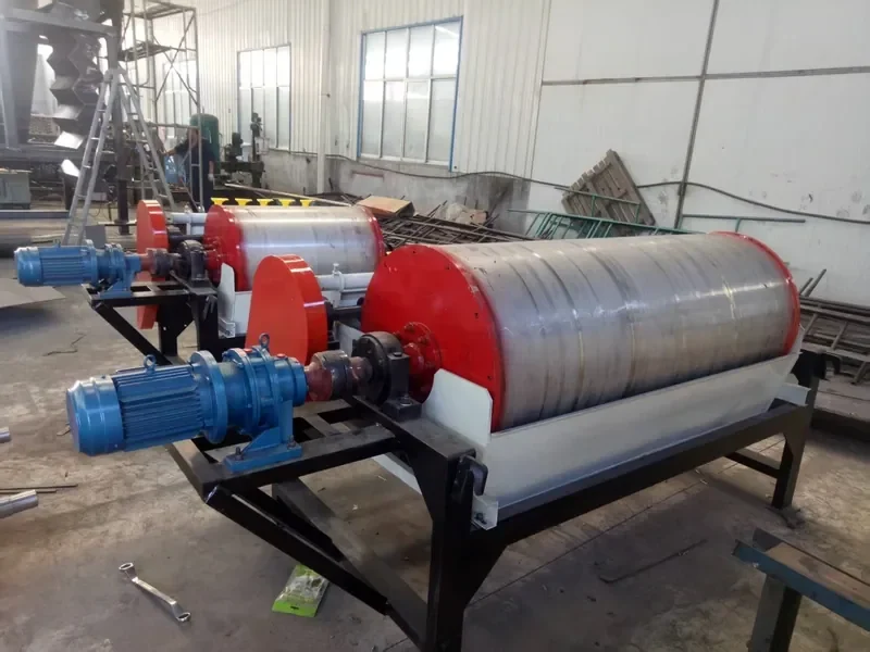
Magnetic separation is a physical process that uses magnetic force to change the path of magnetically responsive material and separate it from a less-responsive stream. A magnetic separator normally works through five stages: feed presentation, magnetic exposure, trajectory change, stream separation, and removal or discharge of the captured fraction.
The same separator can give different results when the target material, particle size, working distance, feed depth, belt or flow speed, moisture, liberation state, or discharge geometry changes. The sections below explain which changes matter, what you may observe, and what to check next.
Choose the path that matches your question. You do not need to read this page as a purchasing guide. Start with the part that helps you understand the process condition you actually have.
What Is Magnetic Separation?
The target may be obvious ferrous tramp metal, such as an iron or steel piece in a bulk stream, or a magnetic mineral in dry ore or slurry. Materials do not all respond equally. Ferromagnetic materials respond strongly, while weakly magnetic minerals may require a different field intensity, field gradient, particle presentation, or separator geometry before a useful split is possible.
Magnetic separation is not the same as metal detection. A detector can sense metal and trigger another action, but detection alone does not capture the piece. It is also different from eddy-current separation, which uses a changing magnetic field to induce currents in conductive non-ferrous metals and create a repulsive force.
If you want to browse equipment families rather than study the principle, start with our magnetic separation equipment category.
How Magnetic Separators Work Step by Step
Different magnetic separator designs look very different, but they all have to create a magnetic interaction, present the feed to it, form two material paths, and manage the captured fraction.
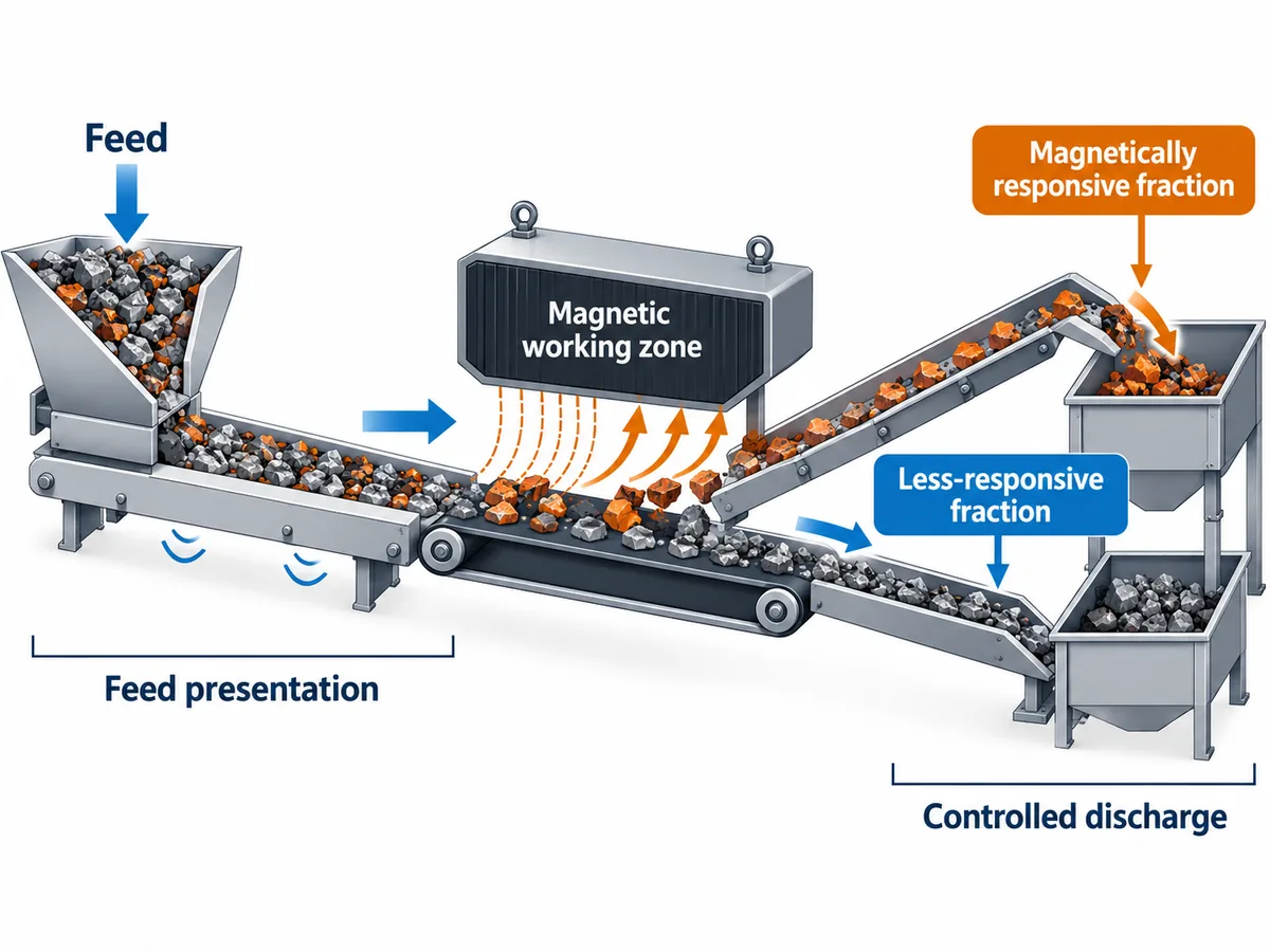
The common sequence is feed presentation, magnetic interaction, stream separation, and controlled discharge. The hardware changes, but these process functions remain.
- Create the magnetic field. A permanent magnetic assembly or electromagnetic circuit creates a field in a defined working zone. The useful question is what field and gradient reach the target at the position where the target actually travels.
- Present the material to that field. The feed may move on a conveyor, fall through a chute, pass around a drum, flow through a pipe, or travel in slurry. Presentation controls the real distance between the target and the magnetic source.
- Change the target path. A responsive particle experiences magnetic force while gravity, inertia, friction, fluid drag, collision, or the main product flow carries it in another direction. A useful separation starts when the magnetic interaction changes the trajectory enough for the process geometry to split the streams.
- Let the less-responsive fraction continue. Material with less magnetic response normally follows its gravity, conveyor, slurry, or discharge path unless another force redirects it.
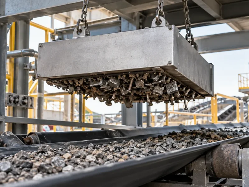
- Transport and release the captured fraction. A drum or pulley can carry magnetic material beyond the active field; a self-cleaning overband can carry tramp iron away from the belt; a grate or tube can hold contamination until cleaning; a high-gradient matrix can capture weakly magnetic particles and release them during a cleaning step.
The core separation condition: a magnetic field alone does not guarantee separation. At the real target position, the magnetic interaction must be strong enough, and act for long enough, to change the target path before gravity, inertia, fluid drag, friction, collision, or the main material flow carries it elsewhere.
What Determines Whether a Particle Is Actually Captured?
Magnetic capture is a force-and-motion problem. The same separator can behave differently when the material, distance, particle size, or process speed changes.
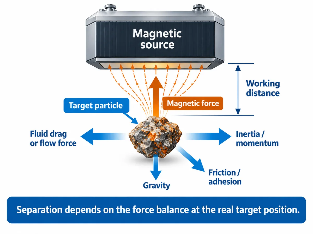
Magnetic separation depends on the force balance at the actual target position, not simply on the presence of a magnetic source.
What Changes When Important Conditions Combine?
Single variables are useful for learning, but real processes often change in combinations. The three cases below are worth separating because the combined condition changes how you interpret the result and what you should check first.
Deep Burden + High Belt Speed
Recognize this situation: tramp iron is carried on a conveyor, some targets are buried below the surface, and the belt is running at a relatively high or recently increased speed.
What you may observe: exposed pieces are captured more consistently than similar pieces buried deeper in the burden.
Why: deeper targets are farther from the magnetic source, while higher speed gives the target less time in the effective working zone. The two conditions act in the same unfavorable direction.
Do not confuse it with: a uniform magnetic-system problem. If surface pieces still behave normally while buried pieces are missed, distance and burden presentation deserve attention before assuming the magnet itself has changed.
Check: burden depth, actual belt speed, target size, target position in the bed, and the real magnet-to-target distance.
Next: compare the missed pieces with the pieces still being captured under the same operating period. That comparison helps separate a presentation limit from a general equipment problem.
Fine + Weakly Magnetic + Wet
Recognize this situation: the target is a fine mineral with relatively weak magnetic response and it is moving in slurry rather than through air.
What you may observe: a simple hand-magnet check suggests some magnetic response, yet the running wet process does not create a clean or stable separation.
Why: weak magnetic response, small particle size, fluid drag, entrainment, flow pattern, and the field gradient all matter at the same time. A static pickup observation removes several of those process forces.
Do not confuse it with: coarse, strongly magnetic material in a wet drum process. Both are “wet magnetic separation,” but they do not present the same capture problem.
Check: particle-size distribution, target mineral response, liberation, slurry condition, flow condition, and whether the test reproduces the wet process rather than only a dry or static contact test.
Next: use a representative wet test before treating a hand-magnet response as equivalent to production performance.
High Surface Gauss + Long Working Distance
Recognize this situation: a datasheet or spot measurement shows a high Gauss value, but the real target is separated from the magnetic source by a belt, housing, sleeve, pipe wall, air gap, or material bed.
What you may observe: the quoted surface number looks strong while capture at the actual target position is weaker than expected.
Why: surface Gauss and the magnetic condition at the target are different measurements. Working distance and field gradient change what the target experiences.
Do not confuse it with: two measurements taken at the same defined location with the same method. Those can be compared more meaningfully than a surface value versus an in-process target position.
Check: measurement location, probe method, non-magnetic gaps, material depth, target position, and the running-process result.
Next: compare magnetic numbers only after the measurement basis and real working distance are defined.
Why Magnetic Separation Results Change in Real Operation
If an existing process changes, start from the symptom you can see. A symptom-first check is usually more useful than assuming every problem means the magnetic source is too weak.
| What you observe | Check first | Then check | Why this helps distinguish the cause |
|---|---|---|---|
| Surface iron is captured but similar buried pieces are missed | Burden depth and real working gap | Belt speed and target size | The symptom points toward distance/presentation before a uniform loss of magnetic function |
| Results worsen after throughput or line speed increases | Bed depth, feed distribution, belt or flow speed | Effective separation-zone length | More material or higher speed can change both target distance and exposure time |
| A hand magnet attracts the sample but production separation is poor | Dry/wet process state and particle size | Magnetic response, liberation, flow, and real geometry | A static contact test removes process forces that exist in a moving production stream |
| One side of the separator performs better than the other | Feed width, depth, and distribution | Alignment and local buildup | The working zone may be loaded unevenly even when the magnetic system is unchanged |
| The two streams separate and then mix again | Splitter position and discharge path | Material trajectory under normal feed | Magnetic capture can be correct while collection geometry fails to preserve the split |
| Performance falls as production continues | Buildup and cleaning condition | Moisture, agglomeration, and product-to-surface distance | Accumulated material can change presentation or increase the effective working distance |
| Magnetic mineral is present, but concentrate or tailing behavior is inconsistent | Particle size and liberation | Feed distribution and process state | A magnetic grain locked to non-magnetic gangue behaves differently from a liberated grain |
Is the limitation magnetic, material-related, or process-related?
Look for a process change first when the same equipment worked acceptably before and the feed rate, speed, moisture, burden depth, slurry condition, or discharge arrangement changed. Look harder at material state when the target size, mineralogy, liberation, or magnetic response changed. Investigate the magnetic system or installation when the abnormal result is broad and cannot be explained by changed material or process conditions. If capture occurs but the final products still remix, treat that as a discharge/collection problem rather than a capture problem.
How the Same Magnetic Principle Changes in Different Processes
The core principle does not change, but the condition you need to recognize does. Use these examples to identify which force balance and process cue is closest to your own line.
Conveyor tramp iron
Recognize it: ferrous pieces move inside a bulk burden on a belt.
What changes the result: burden depth, real working gap, target size and orientation, belt speed, and where the piece sits in the bed.
Different from: free-fall capture, where there is no conveyor burden between the target and the field.
Check next: compare surface and buried misses, then measure burden depth and actual speed. See conveyor magnetic separation and our overband magnetic separator.

Free-fall dry powder or granules
Recognize it: product moves through a chute, hopper, or pipe mainly by gravity.
What changes the result: how evenly the product approaches the magnetic surface, flow velocity, bridging, buildup, and cleaning condition.
Different from: conveyor removal, where bed depth and belt motion dominate the presentation problem.
Check next: observe whether product bypasses part of the magnetic surface or builds a layer that increases the effective distance. See our pipeline magnetic separator.
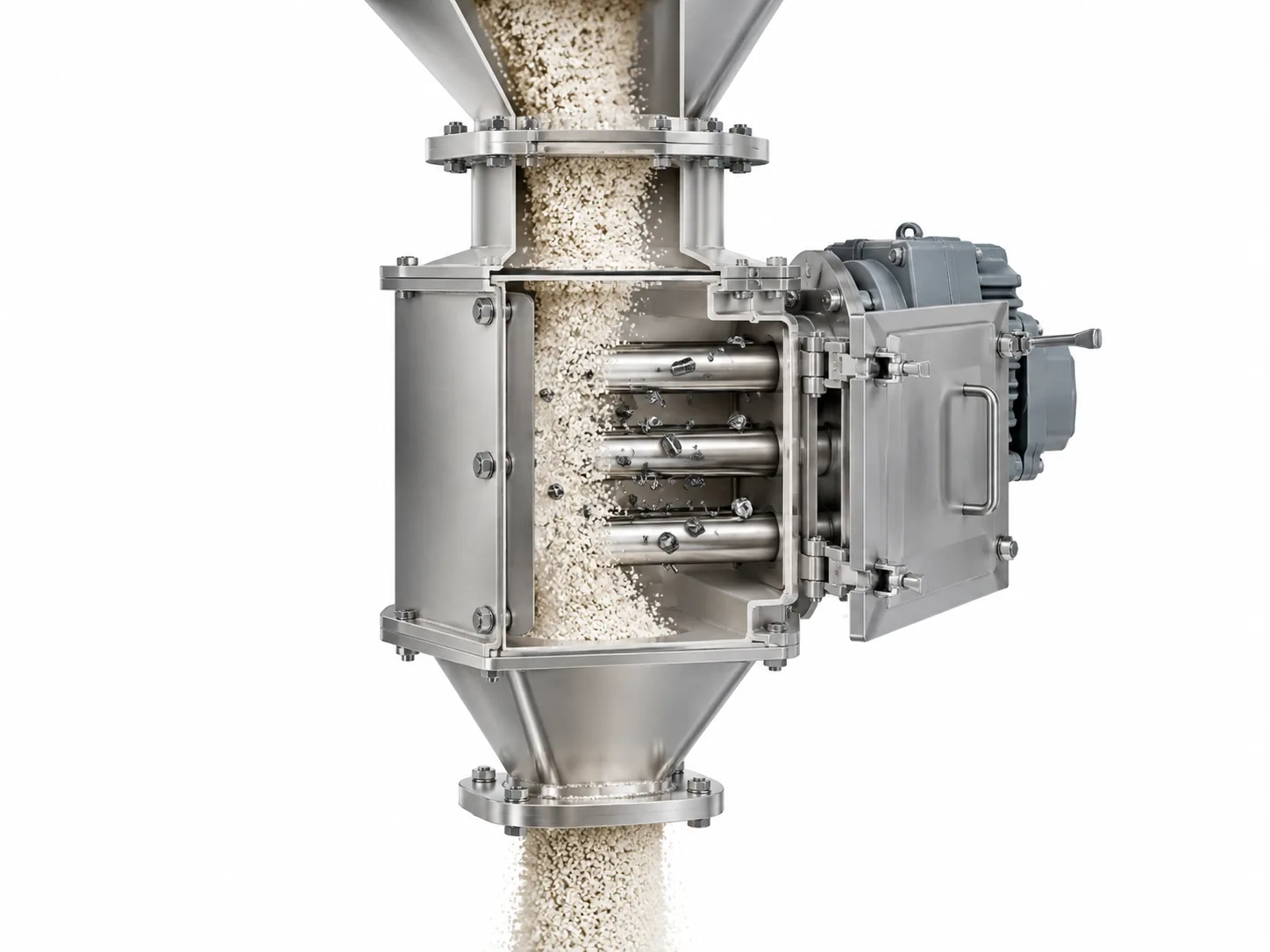
Dry mineral separation
Recognize it: dry particles must follow different trajectories according to their magnetic response.
What changes the result: susceptibility, particle size, liberation, feed layer, splitter position, and discharge geometry.
Different from: tramp-metal protection, where a relatively large ferrous contaminant may be the only target rather than one mineral fraction within a particulate feed.
Check next: confirm whether poor separation begins with weak response, poor liberation, or remixing after the trajectories have already separated. Related applications include iron ore magnetic separation and silica sand iron removal.

Wet, strongly magnetic mineral
Recognize it: a clearly responsive mineral is transported in slurry around a drum or similar wet separation zone.
What changes the result: slurry flow, particle size, tank presentation, entrainment, and how the magnetic product is transported and released.
Different from: fine weakly magnetic work, where field gradient and small-particle behavior become much more important.
Check next: observe both magnetic-product transport and the less-responsive slurry path under representative flow. See our wet drum magnetic separator.

Fine, weakly magnetic mineral
Recognize it: the target is fine, only weakly responsive, and moves in a liquid phase.
What changes the result: susceptibility, particle size, liberation, field gradient, matrix interaction, slurry condition, and flow.
Different from: ordinary wet separation of coarse, strongly magnetic particles; the same “wet” label does not mean the same capture mechanism is limiting.
Check next: use a representative wet test and define the target particle range before drawing conclusions from a hand magnet or one surface field number. For equipment context, see our wet high-intensity magnetic separator.
Dry vs Wet Magnetic Separation: What Changes in the Mechanism?
Dry and wet separators use the same magnetic-response principle, but the forces carrying the particles are different. In dry separation, gravity, conveyor motion, inertia, friction, feed depth, and agglomeration are often important. In wet separation, the target is moving with a liquid phase, so fluid drag, slurry condition, entrainment, and tank or flow geometry become part of the force balance.
A dry pickup test therefore cannot automatically predict a wet mineral-separation result. The same material can behave differently when particle size, liberation, flow velocity, or slurry condition changes. For product-family context, compare our dry drum magnetic separator and wet drum magnetic separator pages; this article keeps the focus on the working principle rather than the full wet-versus-dry selection decision.
Four Common Separation Mechanisms Behind Magnetic Separator Types
There are many equipment names, but the working principle is easier to understand if you first ask how the machine changes and preserves the target path.
| Mechanism | Typical equipment | What mainly changes the result | How to recognize the split |
|---|---|---|---|
| Lift from a moving burden | Suspended / overband magnet | Working gap, burden depth, target size, belt speed | Ferrous pieces leave the main conveyor burden and move toward the overhead collection path |
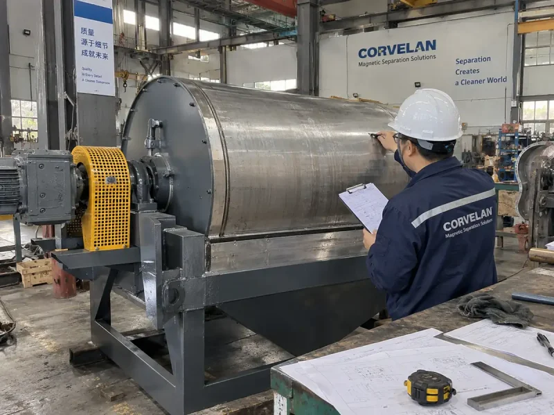
| Hold to a rotating surface longer | Magnetic head pulley, dry drum, wet drum | Particle response, feed presentation, rotation/flow, splitter or tank geometry | Responsive material follows the rotating magnetic surface farther before release |
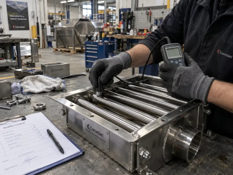
| Capture close to the product path | Pipeline, plate, tube, grate | Product-to-surface distance, flow distribution, buildup, cleaning condition | Ferrous contamination stays on the collection surface while product continues |
| Capture on a high-gradient matrix | Wet high-intensity / high-gradient separator | Susceptibility, particle size, field/gradient, slurry flow, matrix interaction | Weakly magnetic particles remain on matrix elements until the cleaning/release step |
For equipment-level detail, see our magnetic pulley separator, overband magnetic separator, pipeline magnetic separator, and wet high-intensity magnetic separator pages.
Permanent vs Electromagnetic Field Sources
Permanent and electromagnetic describe how the magnetic field is produced, not the complete separation geometry. A permanent magnetic circuit does not need excitation power. An electromagnetic circuit uses energized coils and therefore needs electrical power; cooling and control requirements depend on the design and duty. Either field source can be used within different separator geometries, so the field source alone does not tell you how feed is presented, captured, transported, or discharged.
How to Interpret Gauss, Field Gradient, Pull Force, and Working Distance
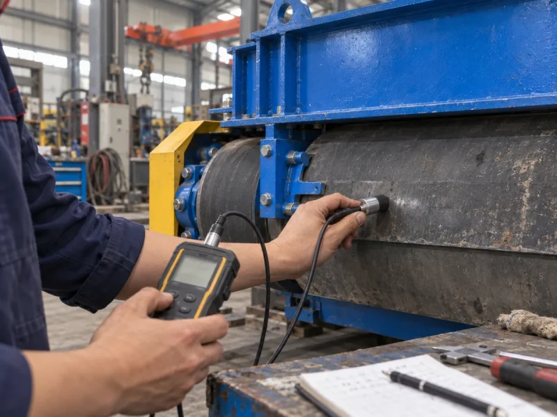
A Gauss or Tesla value describes magnetic flux density at a defined measurement point. It does not by itself show how well pickup or separation will perform at the target’s real operating position.
Why the Same Gauss Number Can Lead to Different Results
Same surface Gauss, different working distance. A target close to the magnetic surface and a target buried behind a belt plus a deep burden are not exposed to the same magnetic condition, even if the quoted surface number is identical.
Same reading, different target material. A strongly ferromagnetic piece and a fine weakly magnetic mineral do not create the same separation response under one field value.
Same separator, different speed or flow. If the material passes through the working zone faster, the time available to change its trajectory also changes.
A Gauss number describes one magnetic condition. Separation describes the interaction of magnetic, material, motion, and geometry conditions.
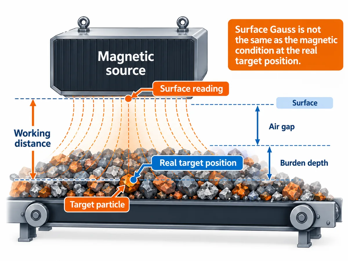
A surface measurement and a value at the real target position are different engineering statements. Always define the measurement location and the working distance.
When Two Magnetic Separator Specifications Look Similar
Do not compare one magnetic number in isolation. Put the two offers on the same basis first: measurement location, measurement method, working gap, target material, target size, belt or flow condition, and cleaning/discharge arrangement. If those conditions are different, the headline Gauss values are not a complete like-for-like comparison.
Before comparing quoted magnetic values, ask where the measurement was taken, how it was measured, what non-magnetic gaps sit between the source and target, and what process test represents the real operating objective. Research on high-gradient magnetic separation also treats particle susceptibility, field strength, field gradient, particle size, and flow conditions as interacting capture variables rather than a one-number problem.
How to Check Whether Magnetic Separation Will Work in Your Process
Before judging whether magnetic separation will work in your process, start with conditions you can observe or measure. Use this sequence before drawing conclusions from one magnetic reading or one quick pickup test.
- Observe the miss or split. Identify what target is being missed, where it is in the feed, whether the problem is uniform across the width, and whether the fractions separate and then remix at discharge.
- Measure the operating condition. Record working distance, burden depth, belt speed or flow condition, target size, feed distribution, and other variables that can change presentation to the field.
- Run a representative test. Keep the target material, particle size, dry/wet state, speed or flow, feed condition, and separation geometry as close to the real process as practical. A static hand-magnet response can be a clue, but it is not a substitute for representative testing when the material is fine, wet, locked, or moving quickly.
- Confirm the installed result. Check that the final equipment produces two stable material paths under normal operating conditions and that cleaning, buildup, or discharge does not undo the separation.
A representative test reduces uncertainty; it does not guarantee identical results for every future feed condition. If the material or operating envelope changes, the separation assumption should be checked again.
Choose the checks that match your situation. If you are learning the principle, identify the target and process state. If you are diagnosing an existing line, compare the current operating condition with the last condition that worked. If you are comparing specifications, normalize the measurement point and process basis. If you are checking material suitability, use a representative sample and a representative dry or wet process test.
Operating Data That Changes the Separation Result
Before discussing a real magnetic separation process, collect enough information to define the problem correctly. These inputs explain the separation challenge; they do not, by themselves, determine the final machine specification.
Material
Target metal or mineral; strong or weak magnetic response; target size range; and, for mineral work, whether the magnetic mineral is liberated or locked to gangue.
Process
Dry or wet condition; throughput; belt speed or liquid/slurry flow; burden depth or pulp condition; moisture, cohesion, agglomeration, and feed distribution.
Installation
Working gap; belt, chute, pipe, or tank geometry; available service and guarding space; and where the magnetic and less-responsive fractions can discharge without remixing.
Objective
Equipment protection, ferrous contamination removal, mineral recovery, or process purification; plus the size and type of target that must be removed or recovered.
Technical References
The working-principle explanations above are consistent with established mineral-processing literature that treats magnetic separation as an interaction between material response, magnetic field/gradient, particle characteristics, and competing process forces.
- Metso, Basics in Minerals Processing — practical mineral-processing reference covering magnetic separation classes and competing forces.
- Zheng et al., Modeling of particle capture in high gradient magnetic separation: A review — review of particle capture in high-gradient magnetic separation.
- Jordens et al., Processing a rare earth mineral deposit using gravity and magnetic separation — discusses magnetic susceptibility, field strength, field gradient, and mineral response in magnetic separation.
Magnetic Separation FAQ
How does a magnetic separator work?
A magnetic separator presents material to a magnetic working zone, changes the path of material that responds strongly enough to the field, lets less-responsive material continue on another path, and then removes or discharges the captured fraction.
Why can a hand-magnet test differ from a production result?
A hand-magnet test is usually static and close-contact. A production process adds working distance, particle size, feed depth, belt or flow speed, fluid drag in wet systems, collision, liberation, and discharge geometry. The hand test can show that a material responds magnetically, but it does not reproduce the full running process.
Does magnetic separation work on all metals?
No. Attraction-based magnetic separation works on materials that are sufficiently magnetically responsive. Iron and many steels are strong targets. Weakly magnetic minerals may need a different field intensity, field gradient, or machine geometry. Conductive non-ferrous metals such as aluminum are commonly separated by a different mechanism, such as eddy-current separation.
Is higher Gauss always better?
No. A higher reading at one point does not automatically mean better separation in the real process. Measurement location, field gradient, working distance, target size and magnetic response, feed speed or flow, and process geometry all matter.
What is the difference between wet and dry magnetic separation?
The core magnetic-response principle is the same. Dry separation is influenced by gravity, inertia, friction, burden depth, and feed distribution. Wet separation adds fluid drag, slurry condition, entrainment, and tank or flow geometry to the force balance.
Is an eddy-current separator the same as a magnetic separator?
It uses a magnetic field, but the separation mechanism is different. Conventional attraction-based magnetic separators redirect magnetically responsive material. Eddy-current separators use a changing magnetic field to induce currents in conductive non-ferrous metals and create a repulsive force.
What determines how far a magnetic separator can capture metal?
There is no universal capture distance. The result depends on the target’s size and magnetic response, the field and field gradient at the target position, the real working gap and burden depth, belt or flow speed, and the forces carrying the target through the process.
How can I tell whether magnetic separation will work on my material?
Start by identifying the target material, particle or tramp-metal size, magnetic response, liberation state if it is a mineral, and whether the process is dry or wet. Then test under representative feed, speed or flow, and geometry. A simple hand-magnet check can be useful as an early observation, but it does not replace a representative process test.
Discuss the Separation Conditions, Not Just the Magnet
For a real project, start with six inputs: target material, target size, dry or wet process state, throughput, belt or flow condition, and an installation drawing or key dimensions. These inputs let us discuss the separation mechanism before comparing equipment configurations.