Find equipment by installation point and separation task.
All magnetic separators →Start with the material or production line you need to protect.
All applications →Compare technologies, check parameters and prepare your RFQ.
All guides →See the factory, quality checks and answers before you request a quotation.
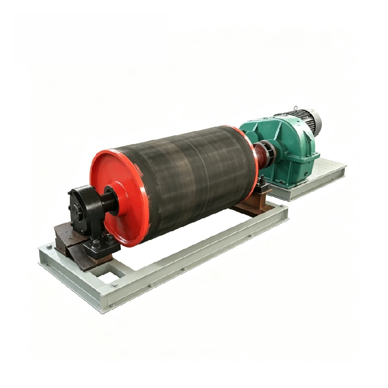
Corvelan magnetic pulleys remove iron and steel as material leaves the end of a belt conveyor. They are also called magnetic head pulleys because they work at the conveyor head. We match the pulley to your conveyor, belt speed, material depth, target iron and discharge layout.
A magnetic pulley works well when your material already moves on a belt conveyor. The conveyor head must also have enough space to keep the normal material and captured iron in separate discharge paths. We check these points before we define the pulley.
Your material already travels on a belt conveyor. The target is iron or another strongly magnetic metal, and there is room at the conveyor head for two discharge paths.
Some jobs need a closer check. Watch for deep or uneven material layers, sticky material and high belt speed. Very small iron pieces, unusual belt contact or limited space for the divider plate, often called a splitter, can also change the result.
If the conveyor head is not the right place, we can review another option. This may be a suspended magnet, a magnetic drum or another magnetic separator.
We start with the job you need the separator to do. That helps us check whether a magnetic head pulley is the right type of separator before we work on detailed dimensions.
Remove tramp iron before it reaches crushers, grinders or other downstream equipment that can be damaged by ferrous pieces.
Separate unwanted iron and steel from the bulk material stream at the conveyor discharge.
Separate magnetic iron and steel into their own discharge stream when the recovered metal has process or recycling value.
We normally use a magnetic pulley when material already moves on a belt conveyor and the target iron responds well to a magnetic field. There must also be enough space for the captured iron to leave through a separate discharge path. How the material sits on the belt also matters. A thin, even layer is easier to separate than iron buried under a deep or sticky layer.
The RCTG and CXG product families cover conveyor iron removal, mineral pre-selection, building materials, steel, power, chemical processing, waste treatment and metal recovery. We still match the separator to the real material, target iron and conveyor condition.
Problem: Waste rock or magnetic ore must be separated after crushing.
Why it may fit: The CXG family is intended for dry pre-selection and can use the conveyor discharge as the magnetic separation point.
Problem: Tramp iron can damage crushers, screens or downstream equipment.
Why it may fit: RCTG family data includes building-material applications where iron is removed at the conveyor head.
Problem: Metallic iron must be recovered from slag or a mixed bulk stream.
Why it may fit: The CXG application data includes metal recovery from steel slag and similar dry material streams.
Problem: Tramp iron must be removed before the next process stage.
Why it may fit: The RCTG family is listed for power and other bulk-handling applications where automatic iron discharge is needed.
Problem: Exposed ferrous pieces must be removed or recovered from waste material.
Why it may fit: Both family data sets include waste-treatment or metal-recovery uses where a conveyor-head separation point is practical.
Problem: Iron or steel pieces threaten downstream equipment.
Why it may fit: A magnetic pulley can combine the conveyor head function with continuous ferrous removal when the discharge geometry is suitable.
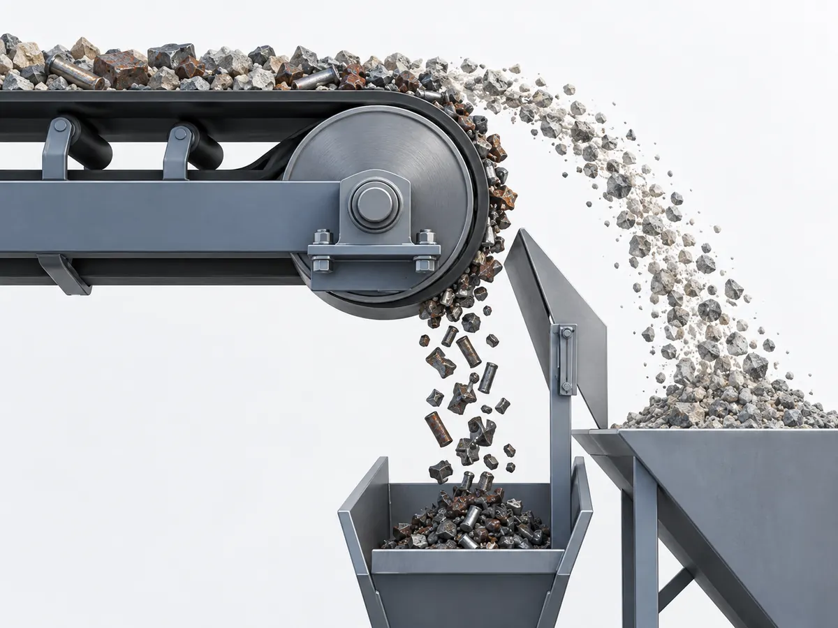
As the belt moves around the magnetic head pulley, most non-magnetic material falls away in its normal path. Iron and other strongly magnetic metal stay with the belt for longer. They stay attached while they pass through the strong part of the magnetic field. Engineers often call this the active magnetic zone. The captured metal drops after it leaves this area. We position the divider plate or chute so the two material streams stay separate.
Bulk material reaches the conveyor head on the belt.
The magnetic field pulls iron and other magnetic metal toward the pulley through the belt and any pulley covering. This covering is often called lagging.
The captured iron stays with the belt while the non-magnetic material leaves the head pulley.
Captured metal drops after it leaves the strong magnetic area and is collected separately.
A single surface Gauss number cannot predict the final separation result. Gauss is a magnetic flux-density reading at a defined point. We also look at the target iron, the distance from the magnet, material depth, belt speed, feed condition and discharge layout.
| What We Check | Why It Matters | What to Send Us |
|---|---|---|
| Distance From the Magnet | The magnetic field must reach through the pulley covering, belt and material layer. Engineers call the distance between the magnet and the target the working distance. | Belt and pulley-covering details, plus the material depth. |
| Material Depth | Iron buried under a deep material layer is harder for the magnetic field to reach. Engineers often call this layer the burden depth. | Normal and peak material depth if known. |
| Belt speed | Speed changes both the time available for magnetic response and the discharge trajectory. | Normal operating speed and any major variation. |
| Target Iron or Steel | Size, shape and magnetic response change how easily the iron or steel can be captured. | Photo, sample description, size range and the result you need. |
| How the Material Feeds | Uneven feed, moisture, sticky carryback and large lumps can hide the iron or make it harder to release cleanly. | Material description, photos and any known moisture or stickiness. |
| Magnetic Area & Discharge Layout | We check how long the pulley holds the iron, how much belt contacts the pulley, where the iron releases and where the divider plate sits. | A conveyor-head drawing, side view or clear site photos. |
No. A higher surface Gauss number does not automatically mean better separation.
A magnetic flux-density reading taken at a stated point. The value changes with measurement position and distance.
Depends on the test object, contact condition, magnetic circuit and test setup. It is not the same as a Gauss reading.
Also depends on target iron, working distance, material depth, belt speed, feed condition and discharge layout.
That is why Corvelan does not select a magnetic pulley from one Gauss number alone. We compare magnetic readings only when the measurement point and method are defined, then review them with the real conveyor condition.
We do not select a magnetic pulley from belt width alone. The pulley must fit the conveyor, the magnetic system must suit the target iron, and the discharge area must keep the two material streams separate.
Have the basic conveyor data already?
Send the belt width, speed, current pulley details and target iron. We can identify the missing inputs before detailed sizing.
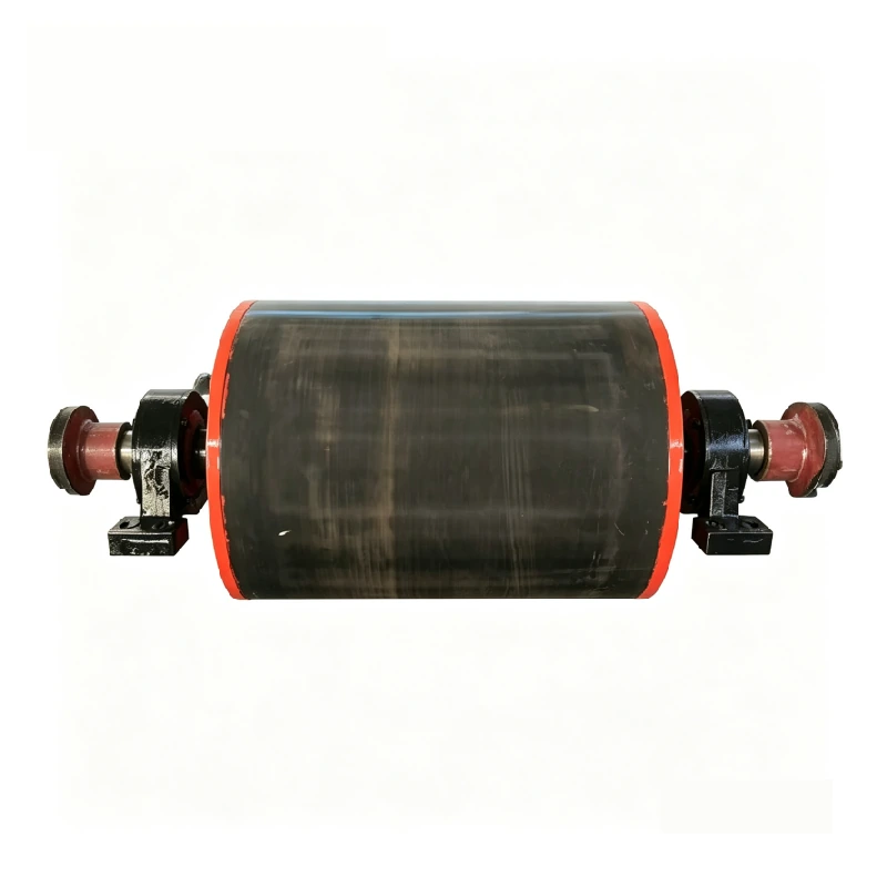
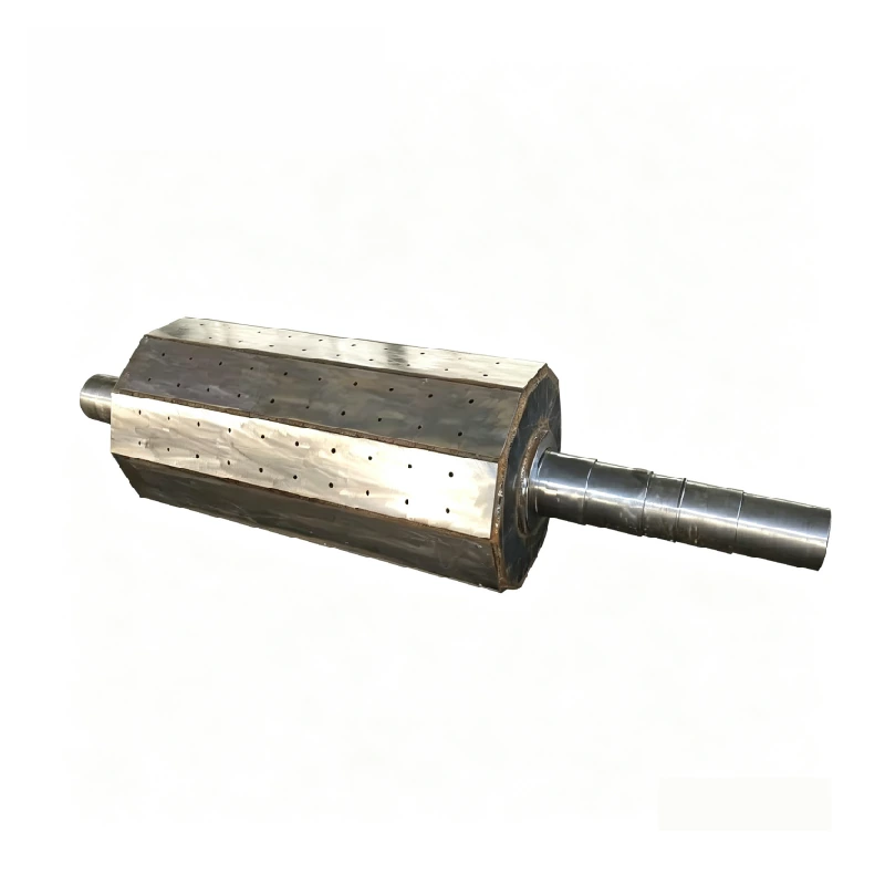
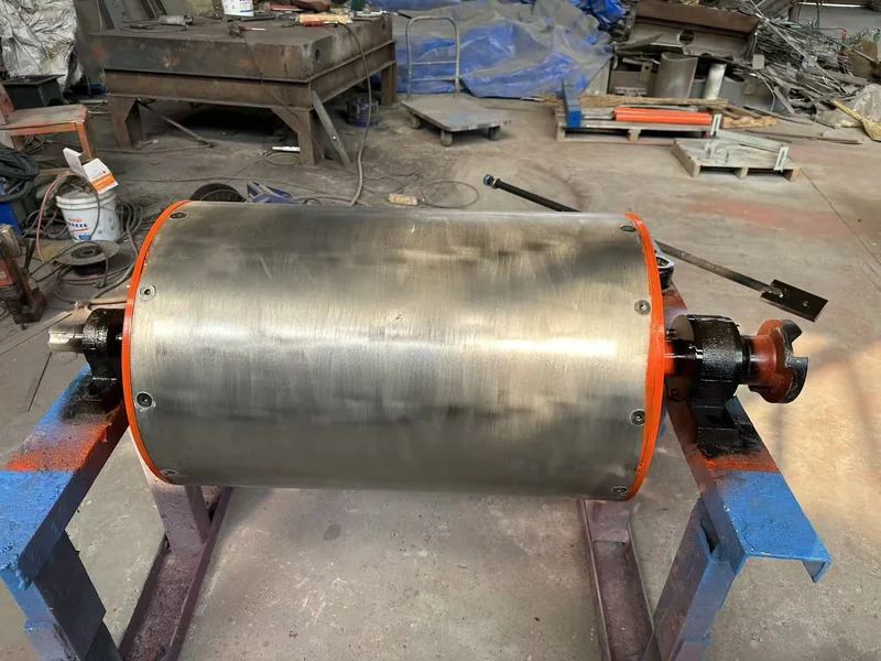
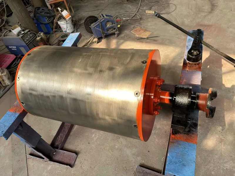
A magnetic pulley must do two jobs at once: support the conveyor belt and create a useful magnetic separation zone. The product photos show the finished pulley, internal permanent-magnet assembly and workshop magnet-block construction.
The rotating shell supports the conveyor belt and forms the working surface around the magnetic system.
The internal segmented permanent-magnet assembly creates the useful magnetic area around the shaft.
The shaft connects the pulley to the bearings and drive arrangement. Final dimensions must match the selected model and conveyor.
Bearing type and mounting centres must fit the conveyor structure and mechanical load.
The RCTG and CXG families include smooth and rubber-lagged configurations. Surface selection affects belt grip, wear and working distance.
The divider keeps the normal material and captured iron in separate paths after discharge.


The current RCTG reference range includes 16 listed models. Use these values as a starting point for model matching; final pulley, shaft and magnetic details are confirmed against the project technical data before production.
| Model | Surface Flux Density | Reference Material Layer | Max. Belt Speed | Drum Ø D | Face Length L | Weight |
|---|---|---|---|---|---|---|
| RCTG-32/40 | 1500 GS | ≤40 mm | ≤2.5 m/s | 320 mm | 500 mm | 150 kg |
| RCTG-32/50 | 1500 GS | ≤60 mm | ≤2.5 m/s | 320 mm | 600 mm | 198 kg |
| RCTG-40/50 | 1550 GS | ≤80 mm | ≤2.5 m/s | 400 mm | 600 mm | 250 kg |
| RCTG-50/50 | 1600 GS | ≤100 mm | ≤2.5 m/s | 500 mm | 600 mm | 370 kg |
| RCTG-32/65 | 1500 GS | ≤70 mm | ≤2.5 m/s | 320 mm | 750 mm | 245 kg |
| RCTG-40/65 | 1550 GS | ≤100 mm | ≤2.5 m/s | 400 mm | 750 mm | 405 kg |
| RCTG-50/65 | 1600 GS | ≤130 mm | ≤2.5 m/s | 500 mm | 750 mm | 520 kg |
| RCTG-50/80 | 1550 GS | ≤100 mm | ≤2.5 m/s | 500 mm | 950 mm | 610 kg |
| RCTG-65/80 | 1650 GS | ≤130 mm | ≤2.5 m/s | 650 mm | 950 mm | 720 kg |
| RCTG-80/80 | 1800 GS | ≤150 mm | ≤2.5 m/s | 800 mm | 950 mm | 980 kg |
| RCTG-65/100 | 1700 GS | ≤130 mm | ≤2.5 m/s | 650 mm | 1150 mm | 910 kg |
| RCTG-80/100 | 1700 GS | ≤170 mm | ≤2.5 m/s | 800 mm | 1150 mm | 1200 kg |
| RCTG-65/120 | 1800 GS | ≤100 mm | ≤2.5 m/s | 650 mm | 1400 mm | 1500 kg |
| RCTG-100/120 | 1800 GS | ≤200 mm | ≤2.5 m/s | 1000 mm | 1400 mm | 1890 kg |
| RCTG-100/140 | 1800 GS | ≤230 mm | ≤2.5 m/s | 1000 mm | 1600 mm | 2160 kg |
| RCTG-125/160 | 1800 GS | ≤260 mm | ≤2.5 m/s | 1250 mm | 1800 mm | 2800 kg |
| Model | A | D | L | L1 | K | Shaft Ø d | h | b |
|---|---|---|---|---|---|---|---|---|
| RCTG-32/40 | 728 | 320 | 500 | 926 | 100 | 45 | 48.5 | 14 |
| RCTG-32/50 | 850 | 320 | 600 | 1097 | 115 | 50 | 53.5 | 14 |
| RCTG-40/50 | 850 | 400 | 600 | 1097 | 115 | 55 | 60 | 16 |
| RCTG-50/50 | 850 | 500 | 600 | 1097 | 115 | 55 | 60 | 16 |
| RCTG-32/65 | 1000 | 320 | 750 | 1280 | 135 | 65 | 69 | 18 |
| RCTG-40/65 | 1000 | 400 | 750 | 1280 | 135 | 65 | 69 | 18 |
| RCTG-50/65 | 1000 | 500 | 750 | 1280 | 135 | 70 | 76 | 20 |
| RCTG-50/80 | 1300 | 500 | 950 | 1580 | 135 | 70 | 76 | 20 |
| RCTG-65/80 | 1300 | 650 | 950 | 1661 | 175 | 70 | 76 | 20 |
| RCTG-80/80 | 1300 | 800 | 950 | 1661 | 175 | 90 | 76 | 24 |
| RCTG-65/100 | 1500 | 650 | 1150 | 1861 | 175 | 90 | 97 | 24 |
| RCTG-80/100 | 1500 | 800 | 1150 | 1954 | 215 | 90 | 97 | 24 |
| RCTG-65/120 | 1750 | 650 | 1400 | 2195 | 215 | 110 | 119 | 32 |
| RCTG-100/120 | 1750 | 1000 | 1400 | 2270 | 255 | 110 | 119 | 32 |
| RCTG-100/140 | 2000 | 1000 | 1600 | 2446 | 255 | 110 | 119 | 32 |
| RCTG-125/160 | 2150 | 1250 | 1800 | 2600 | 255 | 120 | 129 | 32 |
The CXG family is a permanent dry pre-selection magnetic pulley for mineral and metal-recovery applications. It uses a high-strength permanent magnetic system, a stainless-steel drum shell and non-magnetic stainless material between the shaft and magnetic system.

| Model | Drum Length L | Drum Ø D | Smooth-Pulley Allowable Torque | Rubber-Lagged Allowable Torque | Weight |
|---|---|---|---|---|---|
| KS-CXG50 | 600 mm | 500 mm | 1.63 kN·m | 2.5 kN·m | 380 kg |
| KS-CXG65-1 | 750 mm | 500 mm | 2.12 kN·m | 3.26 kN·m | 580 kg |
| KS-CXG65-2 | 750 mm | 630 mm | 2.96 kN·m | 4.54 kN·m | 800 kg |
| KS-CXG80-1 | 950 mm | 500 mm | 2.62 kN·m | 4.01 kN·m | 765 kg |
| KS-CXG80-2 | 950 mm | 630 mm | 3.67 kN·m | 5.61 kN·m | 1090 kg |
| KS-CXG80-3 | 950 mm | 800 mm | 5.59 kN·m | 8.55 kN·m | 1480 kg |
| KS-CXG100-1 | 1150 mm | 630 mm | 4.57 kN·m | 7.01 kN·m | 1285 kg |
| KS-CXG100-2 | 1150 mm | 800 mm | 6.96 kN·m | 10.68 kN·m | 1865 kg |
| KS-CXG100-3 | 1150 mm | 1000 mm | — | 17.75 kN·m | 2795 kg |
| KS-CXG120-1 | 1400 mm | 630 mm | 5.49 kN·m | 8.4 kN·m | 1610 kg |
| KS-CXG120-2 | 1400 mm | 800 mm | 8.37 kN·m | 12.81 kN·m | 2465 kg |
| KS-CXG120-3 | 1400 mm | 1000 mm | — | 21.3 kN·m | 3560 kg |
| KS-CXG120-4 | 1400 mm | 1250 mm | — | 30 kN·m | 5230 kg |
| KS-CXG140-1 | 1600 mm | 800 mm | 9.76 kN·m | 14.92 kN·m | 2865 kg |
| KS-CXG140-2 | 1600 mm | 1000 mm | — | 24.925 kN·m | 4405 kg |
| KS-CXG140-3 | 1600 mm | 1250 mm | — | 35.0 kN·m | 6005 kg |
| KS-CXG140-4 | 1600 mm | 1400 mm | — | 47.0 kN·m | 7535 kg |
The RCTG and CXG ranges give us a real starting point, but the selected pulley still has to fit your conveyor correctly. Send the existing drawing, dimensions and operating data so we can match the reference model and confirm the final shaft, bearings, drive and discharge layout before production.
| What We Need | What We Check |
|---|---|
| Pulley & belt size | Diameter, face width, belt width, belt contact and edge clearance. |
| Shaft, bearings & drive | Shaft size, mounting centres, bearing arrangement and drive connection. |
| Belt speed & wrap | Operating speed and how much the belt contacts the pulley. |
| Material depth | Normal and peak depth where available. |
| Target iron or steel | Type, size, shape, approximate amount and required result. |
| Magnetic requirement | Target response, working distance and required magnetic area. |
| Divider / chute | Space for two discharge paths and material collection. |
| Surface & environment | Belt grip, wear, temperature, dust, moisture, corrosion and site limits. |
Quick Fit already tells you when a magnetic pulley is a strong starting point. We move to another route when the conveyor head cannot present the target or discharge the captured iron cleanly.
If the iron stays buried too far from the pulley, we may review an upstream separation point or a suspended conveyor magnet.
If the process needs its own feed, rotating separator and controlled splitter, a magnetic drum may be the better route.
Aluminum, copper and similar metals need another separation method unless they are attached to a strongly magnetic iron-based part.
If the head cannot provide two stable material paths, we review another installation point or separator type.
Not sure which type of separator fits?
Send us the material, target iron and conveyor layout. We can check the separation route before you spend time on detailed pulley dimensions.
These separators can all remove ferrous material, but they solve different layout problems. Choose from the process position, material presentation, working distance and the place where captured iron can be discharged safely.
| Question | Magnetic Pulley | Magnetic Drum | Suspended Magnet |
|---|---|---|---|
| Where does it work? | At the conveyor head / discharge end. | At a separate controlled feed and discharge stage. | Above a conveyor or transfer point. |
| Does it replace the head pulley? | It can, when the conveyor dimensions and discharge layout allow it. | No. It is a separate rotating separator. | No. It works above the main conveyor. |
| Good starting point when | The head end is already a practical separation point and two discharge paths can be created. | The feed can be controlled and split into magnetic and non-magnetic discharge paths. | Tramp iron must be removed before the conveyor discharge or before vulnerable equipment. |
| Deep or uneven material layer | Needs careful review because buried iron is farther from the magnetic source. | Can be reviewed with a controlled feed and drum arrangement. | Working distance and burden depth are key selection inputs. |
| Retrofit impact | May replace the existing head pulley when the shaft, bearings, belt and discharge layout can be matched. | Usually adds a separate separator stage. | Needs overhead mounting space and a suitable support structure. |
| Main project inputs | Pulley fit, belt speed, material depth, target iron and discharge layout. | Feed condition, layer depth, drum arrangement, speed and splitter position. | Burden depth, working distance, belt speed, target iron, cleaning method and mounting space. |
| Where to learn more | This page. | Review the controlled-feed separator route during the application review. | See conveyor magnet selection → |

Suppose a belt conveyor carries aggregate toward a crusher and the target is tramp iron. This example shows how target metal, material depth and conveyor conditions affect preliminary magnetic-pulley selection.
Is the target strongly magnetic iron or steel, and what size and shape must be removed?
Can the target get close enough to the magnetic field through the belt, pulley covering and material depth?
Can the head pulley, shaft, bearings, belt contact and drive arrangement be matched to the magnetic pulley?
Is there enough space for the normal material and captured iron to leave through separate, stable paths?
A magnetic pulley can replace an existing head pulley in some projects, but we first confirm the mechanical fit and the space for two discharge paths.
Send the drawing or the diameter, face width, shaft, bearings and drive details.
We check belt width, speed, belt contact, tracking and available space.
We check where normal material and captured iron will fall and where the divider should sit.
We confirm the final dimensions and any required checks before production.
Before magnetic performance, we check the pulley body, shaft, bearings, belt contact and surrounding structure.
| If Available | Send Us |
|---|---|
| Existing pulley & drive | Drawing or main dimensions, shaft, bearings and drive-side details. |
| Belt | Width, normal speed and known tracking or load information. |
| Material & target iron | Material description plus target-iron photo, size and shape if available. |
| Available space | Side-view photo or layout showing the head, chute, frame and collection area. |
Have an existing head-pulley drawing?
Send it with the material and target iron. If not, send clear photos and the dimensions you already have.
The magnetic pulley separates continuously, but the conveyor and discharge area still need routine inspection. The main checks are the parts that can change the distance from the magnet, belt tracking or the two discharge paths.
Inspect the belt condition, alignment and pulley covering. Wear or buildup can change the distance between the magnet and the target iron.
Maintain the bearings, shaft and mounting parts as part of the conveyor service plan. The RCTG family data also describes a detachable shaft arrangement intended to simplify service.
Remove buildup and make sure captured iron cannot fall back into the normal material stream.
Keep the collection area clear and large enough for the amount of captured iron.
Follow the final conveyor guarding, lockout and site safety requirements during inspection and service.
Before we use a test result, we agree on the test method. This keeps dimensions, magnetic readings and separation checks tied to the real conveyor condition.
| What We Check | How We Check It |
|---|---|
| Pulley Fit and Dimensions | Compare pulley, shaft, bearing and installation dimensions with the agreed project data. |
| Magnetic Field Check — if required | Define the instrument, probe direction, measurement point and distance first. |
| Separation Test — if required | Define target iron, material depth, belt speed, test passes and pass/fail rule. |
| Discharge Check | Check the divider or chute, both material paths and the collection area. |
| Final Check Record | Record the dimensional, magnetic or separation checks included in the project. |
If you need a drawing, magnetic record or separation test record, include it in the quotation scope before production.
Send the material and conveyor information. We turn it into a defined separator route, pulley fit and final check plan.
We first decide whether the RCTG conveyor-head route, the CXG dry pre-selection route or another separator is the better fit.
We compare drum diameter, face length, material depth, belt speed and the available reference sizes.
We check shaft, bearings, drive, belt contact, installation space and discharge paths.
We confirm the drawing and any required dimensional, magnetic or separation check before production.
These are the questions we most often answer before we select and size a magnetic pulley for a conveyor.
You do not need a finished specification before contacting us. Send what you already know. We will tell you what else we need after the first review.
Send the information already available and we will identify the remaining data required for final selection.
Send us your material, target iron, throughput and the conveyor information you already have. We will check whether a magnetic pulley fits the job and tell you what we need next.