Check recovered wood for nails before a shredder with a plan that both finds the metal and keeps it out of the infeed. Remove loose magnetic iron where it can be captured. Use a suitable conveyor metal detector to find remaining hazards, then stop and remove the affected wood or divert it into a separate stream.
If you are looking for a metal detector for wood nails before a shredder, start with one question: are the nails loose, or still fixed inside the wood? A magnet can lift a loose steel nail. It cannot be relied on to pull every nail out of a heavy board. Also separate protection of the first shredder from cleaning wood that has already been shredded. Those are different jobs.
What metal must be kept out of your shredder?
Define the metal your particular shredder must exclude, using its permitted feed specification and the objects found in your incoming wood. A machine designed for nailed pallets has a different duty from a chipper or secondary shredder that needs cleaner feed. Do not use the word “shredder” as a common metal-tolerance rating.
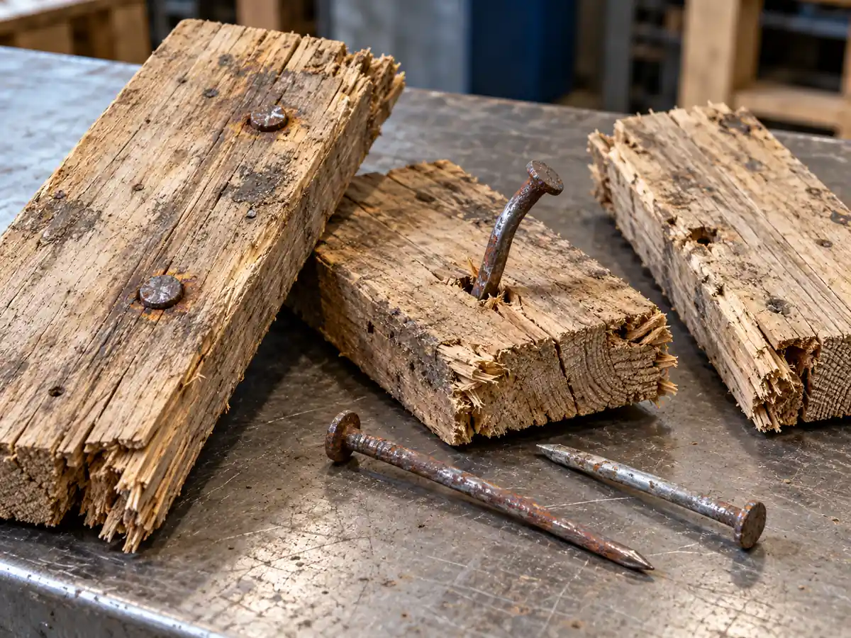
Start with recovered fasteners, maintenance finds, damaged cutting parts, and the machine’s feed requirements. Keep examples of whole nails, broken nail shanks, screws, wire, brackets, and other damaging items. Record their material and dimensions, including nail diameter and length. A short, thin nail fragment is a different detection target from a large bolt.
| What arrives with the wood | First action to consider | What still needs a separate decision |
|---|---|---|
| Loose steel nails, screws, or wire | Magnetic removal before the protected machine | Whether the magnet captures them through the actual wood layer |
| Nails or screws embedded in boards | Detect and remove the contaminated board, or de-nail it off the line | Whether the detector finds the required target at its hardest position |
| Large brackets, hinges, and visible hardware | Remove during incoming sorting where safely accessible | Hidden metal left in the same piece |
| Aluminum, brass, or weakly magnetic stainless parts | Detection with a defined removal action | A conventional iron-removal magnet will not handle every metal type |
For a primary shredder that is specified to process nailed wood, routine fasteners may be part of the accepted feed. The protection target may instead be larger hardware or other prohibited objects. That choice must come from the machine’s accepted feed, not from a decision to lower detector sensitivity until alarms disappear.
Metal control also supports the site’s fire precautions, but it is only one part of them. Wood dust, hot material, batteries, and other ignition sources need their own controls.
Where should detection and removal sit in the wood line?
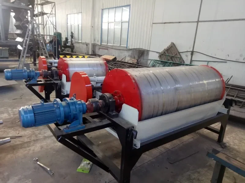
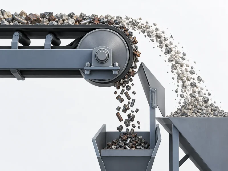
Place each step before the machine it is meant to protect, and leave enough space for the detected wood to stop or leave the main stream. Use magnets for metal they can physically extract. Use the detector and its stop or reject arrangement for the hazards that remain.
Intact boards and pallets
For wood that must be cleared before its first size-reduction step, start with incoming sorting and controlled feeding. Spread the pieces so the inspection zone is not buried under an uncontrolled pile. Remove accessible large hardware and free iron, then inspect the remaining wood with a detector suited to the full occupied area.
After detection, remove the affected board or pallet section to a separate work area. Pull accessible fasteners using suitable tools, or keep the whole piece out of that feed stream. Reinspect wood that will return to the line; pulling out one nail does not account for another nail or a broken tip.
An upstream magnet is useful only for what it can extract at that point. A steel nail fixed deep in thick timber may remain attached even when the detector can find it. If routine embedded nails must all be excluded, plan for de-nailing or diversion of contaminated wood rather than relying on an overhead magnet alone.
Wood after an approved primary shredding stage
If the primary shredder is designed and approved for the nailed feed, size reduction can release fasteners for later removal. Magnetic separation after that stage can then remove liberated iron before a more sensitive secondary machine. A further detector checks the material that continues toward that machine.
This distinction appears in Bunting’s published wood-recycling process: much of the metal removal follows initial shredding, and a detector checks feed before secondary shredding. Cleaning after the primary shredder protects later equipment; it does not protect the primary shredder from material it has already processed.
Keep the metal collection bin and rejected wood separate from accepted feed. Include access to empty the bin and inspect wear caused by sharp fasteners. A layout that drops recovered nails back onto the conveyor has not completed the removal job.
Should you use an underbelt or surrounding detector?
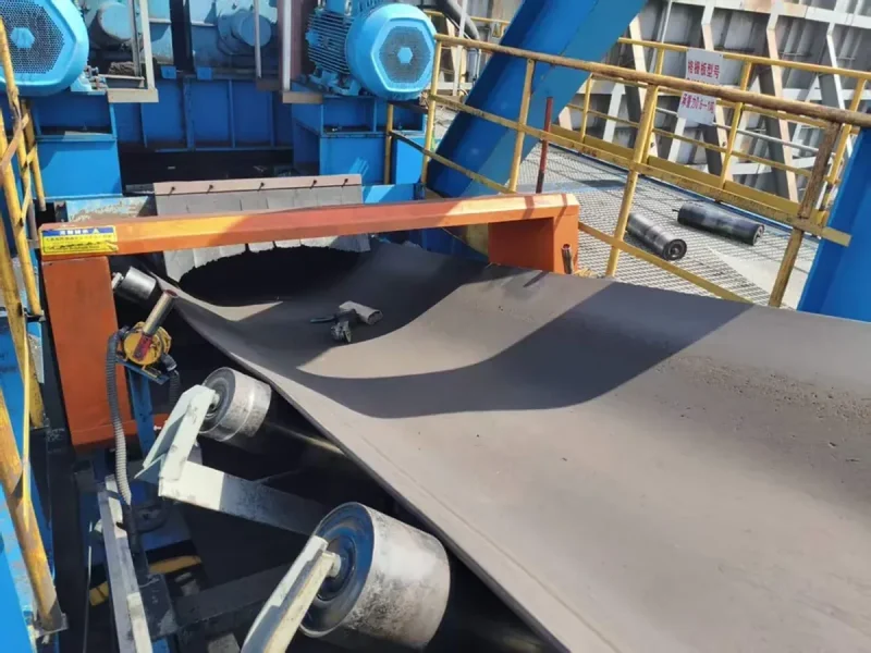
Compare an underbelt detector when space around the conveyor is restricted; compare a surrounding detector when deep loads or high-positioned small targets make underbelt inspection difficult. The final choice needs the actual nail targets, their positions, and the wood layer used in the trial.
Our LJT-H underbelt conveyor metal detector places its sensor below the belt. It is a candidate for wood conveyors where that compact arrangement fits. The key question is how far the hardest target can sit above the sensor, including the belt, installation gap, and full material depth.
Our LJT-E conveyor metal detector uses a sensing zone around the conveyor and is another candidate for bulk wood feed. Compare that arrangement when the required target may be near the top of the load. Leave room for irregular pieces to pass without striking the detector frame.
| Your conveyor condition | Starting point | What decides whether it works |
|---|---|---|
| Little space above or beside the belt; controlled wood layer | Review LJT-H underbelt fit | Required target detected at the farthest relevant position |
| Deep or uneven load; small fastener may ride high | Compare LJT-E surrounding layout | Loaded target tests across the usable inspection area |
| Large boards, pallets, or pieces that can bounce | Review the full moving envelope first | Clear passage plus detection of embedded targets |
| Steel cords, metal clips, or repair fasteners in the belt | Review belt construction before either selection | Stable belt operation without masking required contamination |
Measure normal and maximum material depth at the proposed inspection point. Record belt width, profile, and actual operating speeds. For intact wood, also measure the largest piece and the height it can reach when pieces overlap.
Then define the metal: a drawing or sample should show its material, diameter, length, and whether it is loose or embedded. A large loose bolt passing beside the sensor does not establish detection of a short nail shank near the top of a loaded belt. Test elongated targets in more than one direction because orientation can change the signal.
Keep the detector location clear of interference according to its installation drawing. Nearby steelwork, vibration, motors, cables, and magnetic equipment need to be included in the installation review. There is no useful universal sensitivity or magnet-to-detector spacing that can replace this work.
How far upstream must the detector be installed?
Install the detector far enough upstream that the contaminated wood stops before the point where it can slide, fall, or be pulled into the shredder. Measure the complete response under load. Stopping the drive motor does not instantly stop the belt or everything resting on it.
Mark the detection reference position and the first point beyond which material cannot be safely recovered. That point may be the discharge edge or feed rolls, rather than the cutting rotor. Include the signal path, control delay, belt coast, and wood movement relative to the belt.
Use a controlled commissioning method with the dangerous infeed made safe and the test material recoverable. Record travel from the detector signal until the belt stops, using a belt mark and distance measurement, video, or the conveyor’s position data. Observe whether wood continues to slide or roll. Repeat for the operating conditions that give the longest travel.
Check the leading end of long timber
A nail near the trailing end may trigger detection after the front of the board is already much closer to the shredder. Add that forward reach to the distance needed for stopping and sliding. A plan based only on the nail’s position can miss this failure.
For an initial distance budget, suppose the following conditions apply:
| Assumed input | Value |
|---|---|
| Belt speed during control delay | 1.0 m/s |
| Delay from metal signal to braking action | 0.25 s |
| Belt travel after braking begins | 0.80 m |
| Wood overhang ahead of the detected nail | 1.40 m |
| Additional wood sliding relative to the belt | 0.30 m |
The travel and reach add up to 1.0 × 0.25 + 0.80 + 1.40 + 0.30 = 2.75 m, before adding the project’s allowance for measurement variation and operating conditions. A detector only 2 m from the point of no return would be too close under these assumptions.
If you measure the full belt travel from the metal signal to standstill directly, use that result instead of adding delay travel and braking travel again. Add the wood’s forward reach and extra sliding separately. Take the final installation distance and any retaining arrangement through the conveyor and shredder control design.
Where space is insufficient, move the detector upstream, shorten or separate the feed pieces, or redesign the feed restraint and removal arrangement. An alarm-only output is not a solution when the wood can reach the infeed before anyone can respond.
What should happen after a metal alarm?
The line must hold or divert the affected wood, remove it from accepted feed, and require a controlled restart. Choose stop-and-remove for manageable event rates. Use an engineered reject arrangement when production needs a continuous response and the material can be diverted reliably.
For a stop-and-remove plan, set out the following sequence:
- Stop the affected conveyor and prevent upstream feeding from piling material into the search area. The control design must account for connected feeders and transfers.
- Make the retrieval area safe before access. Isolate and lock out the relevant equipment and control stored energy, moving parts, and wood that could fall or slide. A detector’s process stop is not an energy-isolation device. HSE’s machinery maintenance guidance explains these isolation principles.
- Identify the affected wood. Use the known detection position, measured run-on, and any agreed marking system. A suitable handheld detector can help locate the metal in removed wood on a non-metallic work surface.
- Remove the metal or the whole contaminated piece. Keep recovered objects and rejected wood out of the return feed. If a fastener breaks, account for its remaining shank or tip before returning that piece.
- Reinspect material intended to return, then clear the area and reset through the agreed restart procedure. Record the alarm, recovered item, removal action, and person authorizing the return to service.
If the metal cannot be found, keep the affected material isolated and search it in smaller, controlled portions. Do not restart the same suspect wood merely because resetting the detector clears the alarm. Expand the search to the mapped run-on area if the original search position was uncertain.
For automatic diversion, define the section of wood to reject, how the reject mechanism tracks it, and what happens if the mechanism fails or the collection area fills. Include the largest pieces: a long board can bridge a flap or straddle accepted and rejected streams.
If every batch of nailed boards causes repeated stops, identify what is being recovered. Loose ferrous nails may justify better upstream magnetic capture. Embedded fasteners call for off-line de-nailing, source sorting, or a processing route with a primary machine approved for that feed. Lowering sensitivity simply to keep production running removes part of the protection target.
How do you test detection and actual removal?
Test the required metal targets inside representative wood at the difficult positions, then prove that the affected material is stopped or rejected and recovered. Record detection and physical removal as separate results. An alarm is only the first result.
Before testing, agree which targets must be excluded and what constitutes a failed trial. Use representative whole nails and broken pieces where each matters. Record metal type, diameter, length, embedded depth, and orientation. Secure and identify each target in an approved recoverable carrier or wood sample so it cannot become uncontrolled contamination.
Keep test targets from entering the shredder. Arrange the trial with the machine and conveyor team, using an isolated receiving area or other engineered recovery setup. Keep people outside moving equipment and retrieve samples only after safe isolation.
Start by running the belt without material and then with representative clean wood. Observe the splice passing and nearby equipment operating. That establishes whether the installation is stable before a metal challenge is added.
| Trial condition | What to demonstrate | If it fails |
|---|---|---|
| Target near the belt, mid-layer, and highest required position | Detection through the full material depth | Reduce or control the layer, change the sensing arrangement, and retest |
| Target at the center and relevant edge positions | Coverage across the occupied belt width | Correct feed position or detector coverage |
| Nail along, across, and at other relevant angles to travel | Required elongated targets are not missed in one orientation | Review the target and setup; do not accept only the easiest direction |
| Embedded target in representative thick or overlapping wood | The real wood arrangement still allows detection | Change presentation or candidate equipment |
| Long timber with metal near its trailing end | The leading end stays clear of the infeed | Correct distance, run-on, or feed restraint |
| Required line speed and maximum permitted layer | Detection and the complete line response both work | Repair the failing part and repeat the affected trials |
| Detector unavailable, failed stop output, or reject mechanism unavailable | Feed is held or otherwise kept from the protected machine under the agreed control design | Correct the fault response before relying on the protection system |
Log each pass with target ID, wood condition, position, direction, speed, layer depth, detector settings, and four outcomes: detected; held or diverted; target recovered; restart completed correctly. For a magnet, separately observe capture, retention, and discharge into the metal bin. A piece that falls back into accepted wood is a removal failure.
Choose repetition and acceptance requirements for the agreed protection duty. A single successful pass is not enough to characterize a variable wood stream. If a required position is missed, keep that condition outside the accepted operating range until the cause is corrected and the relevant trials pass.
Keep this record as the reference for routine checks and changes to speed, feed depth, belt repairs, detector position, or control settings. Also review recovered objects: a rising number of loose nails after the magnet and frequent embedded fasteners require different corrective work.
Build the plan around the wood you actually process
A metal detector for nails in recovered wood needs a working removal plan before it can protect a shredder. Separate loose iron from embedded fasteners, match detection to the deepest required target, and give the complete line enough distance to hold or divert the wood. Where initial shredding is used to release nails, that first machine must be suitable for the incoming feed.
To discuss LJT-H or LJT-E fit, use our contact form to send the wood type, largest piece, normal and maximum layer depth, belt width and speed, nail dimensions, and the response you need after detection. Add the available distance to the infeed and any existing magnet. We can review the detector arrangement and required interfaces from these details. Use the message field for the initial information and agree a channel for conveyor drawings or photos in the follow-up.
Recovered wood metal detection FAQs
Can wet recovered wood cause more detector trips than dry wood?
A change in moisture can change the material’s background signal, so compare the actual wet and dry feed before changing sensitivity. Run representative clean material in each condition, then repeat the same required metal targets. If clean wet wood causes trips, review the product setup and installation. The adjusted setup must still detect the required contamination.
We pulled out a nail, but the board still triggers. What should we do?
Keep the board isolated and look for a broken tip, another fastener, or other hidden metal. Compare the recovered nail with its expected length. Scan the board from more than one face using a suitable detector in an area clear of interfering metal. If the remaining source cannot be located and removed, keep the whole board out of the protected feed.
Why does the detector alarm once per belt revolution?
An alarm that follows the same belt position points toward a splice, repair fastener, or metal carried by the belt. Mark the splice and compare its passage with the alarm timing during a safely arranged empty-belt check. Also look for loose metal lodged in the belt. If splice compensation is used, include the required contamination target during that passage in the agreed test; suppressing a splice signal must not silently remove required coverage.
Can we increase conveyor speed after the line passes its test?
Retest detection and the full stop or reject action at the new speed before accepting that operating condition. Higher speed changes the available response time and stopping travel. If feed also increases, measure the new layer depth. Keep the previously accepted operating range until the changed condition is demonstrated.
Can a handheld detector replace the conveyor detector?
A handheld detector can support an off-line inspection or help find metal after an alarm, but it does not automatically cover a whole moving wood stream. Its useful depth, scan spacing, and directions must suit the board and target. An operator checking a few exposed surfaces cannot establish inspection through an overlapping pile. For batch de-nailing, define and test the scan method for each piece; for continuous feed, use a system proven across the full inspection area.