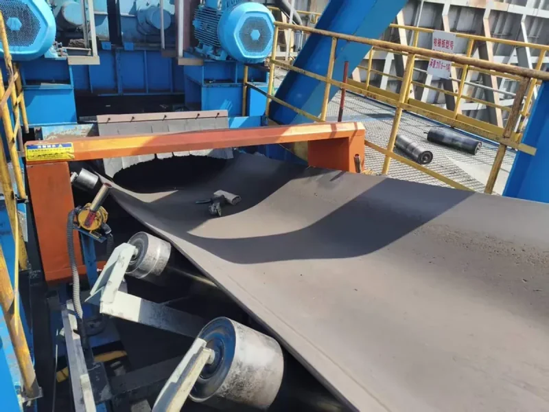
Choose an underbelt metal detector when space above or around the conveyor is limited and it can detect your target throughout the working material layer. Compare a frame-type detector first when small metal or a high material load makes that task harder. The final choice needs two answers: will it fit, and will it find the required metal under your operating conditions?
For an underbelt vs frame metal detector comparison, start with the target metal, normal and maximum material depth, and a conveyor cross-section. Belt width alone answers only part of the installation question. This guide compares industrial conveyor detectors for bulk material; “frame-type” here means a detector around the conveyor, rather than a walk-through security gate.
What changes between underbelt and frame-type metal detectors?
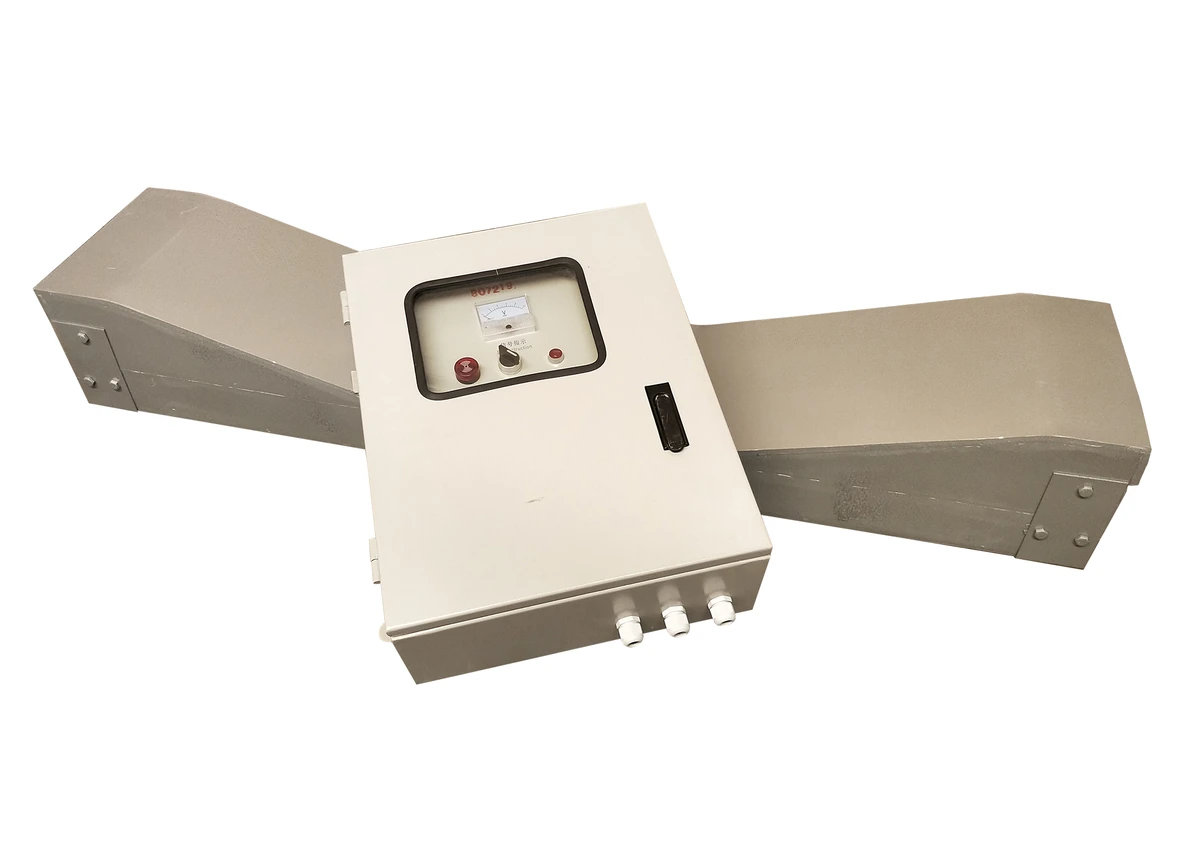
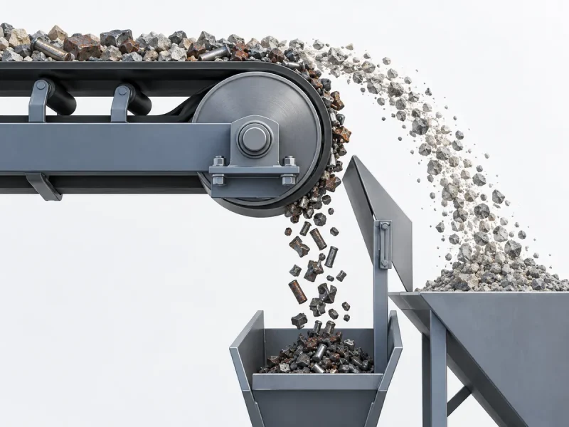
An underbelt detector places its sensing element beneath the belt. A frame-type detector surrounds the conveyor path, so the belt and material pass through its sensing opening. Both detect unwanted metal and send a signal; removing that metal needs a separate line action.
The difference changes where you need space and how targets pass through the sensing area. It does not tell you the complete coil arrangement, electronics, or achievable sensitivity. Two underbelt designs can have different requirements even when they look similar.
| What you compare | Underbelt detector | Frame-type detector |
|---|---|---|
| Space around the conveyor | Keeps the area above the load open; needs usable space below the carrying belt. | Needs room around the conveyor, including clearance above the highest normal load. |
| Target position | Metal farther above the sensor can be harder to detect. | Performance varies within the opening; identify and test the weaker positions. |
| Belt profile | Match the sensor to the flat or troughed belt. | Match the opening and mounting arrangement to the complete conveyor cross-section. |
| Existing-line installation | Often worth checking where a surrounding frame is difficult to fit. | Installation depends on whether the actual frame can open or split and how it mounts. |
| Nearby steel | Requirements depend on the specific sensor design. | Requirements also depend on the specific detector and its mounting arrangement. |
| After detection | Needs the agreed alarm, stop, marking, or reject system. | Needs the same response planning. |
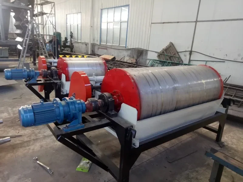
Our LJT-H underbelt conveyor metal detector is the underbelt option to compare. Our LJT-A conveyor metal detector uses a frame-style structure around the conveyor path. Choose between these layouts from the material and installation conditions below, then use the product pages for model information.
Which detector fits your target metal and material depth?
Start with underbelt detection when larger loose metal is the concern and the sensor can cover every required target position. Compare a frame-type detector first when the target is small or the load puts it far above an underbelt sensor. Neither layout has one universal maximum material depth.
Material depth, also called burden depth, is the height of the load on the belt. For an underbelt sensor, a target near the belt can be easier to find than the same target near the top of a high load. Saflec’s undersearch-coil explanation describes the loss of sensitivity as metal moves farther from the coil surface. “Buried metal” is therefore not a precise test position: metal buried near the belt and metal at the top of the load are different challenges.
Define the metal before comparing sensitivity
Specify the metal type, dimensions, shape, and the positions where it must be found. A steel bolt, a stainless steel strip, and an aluminum fragment of similar overall length need different tests. Include unfavorable orientations for long or thin pieces. A test sphere gives a repeatable reference, but it does not represent every wire, washer, or torn strip.
Collect a sample of the damaging part if you can. Otherwise, photograph it next to a ruler and state its material. Avoid a request such as “detect all metal” when the real task is finding a particular bolt or broken tool before a crusher.
Measure the load where the detector will sit
Use the normal and maximum operating load profile at the proposed detector location. Measure during a planned stop with the conveyor isolated, or use an existing profile measurement system. Record height above the carrying belt at the center and toward both sides; include normal surges and belt sag.
An underbelt sensor must follow the conveyor profile closely enough for the job while keeping safe operating clearance. Our LJT-H has flat-type and V-type sensor options; the conveyor cross-section determines which to review. A surrounding frame needs enough opening for the belt, load, and normal movement. Enlarging that opening can also change detection performance.
If the underbelt layout fits but misses a target at the upper part of the load, compare a frame or another installation position. Reducing and stabilizing material depth is another option, provided the belt and downstream equipment can still handle the required output. Do not reduce the load without checking what that does to tonnes per hour.
What must fit on an existing conveyor?
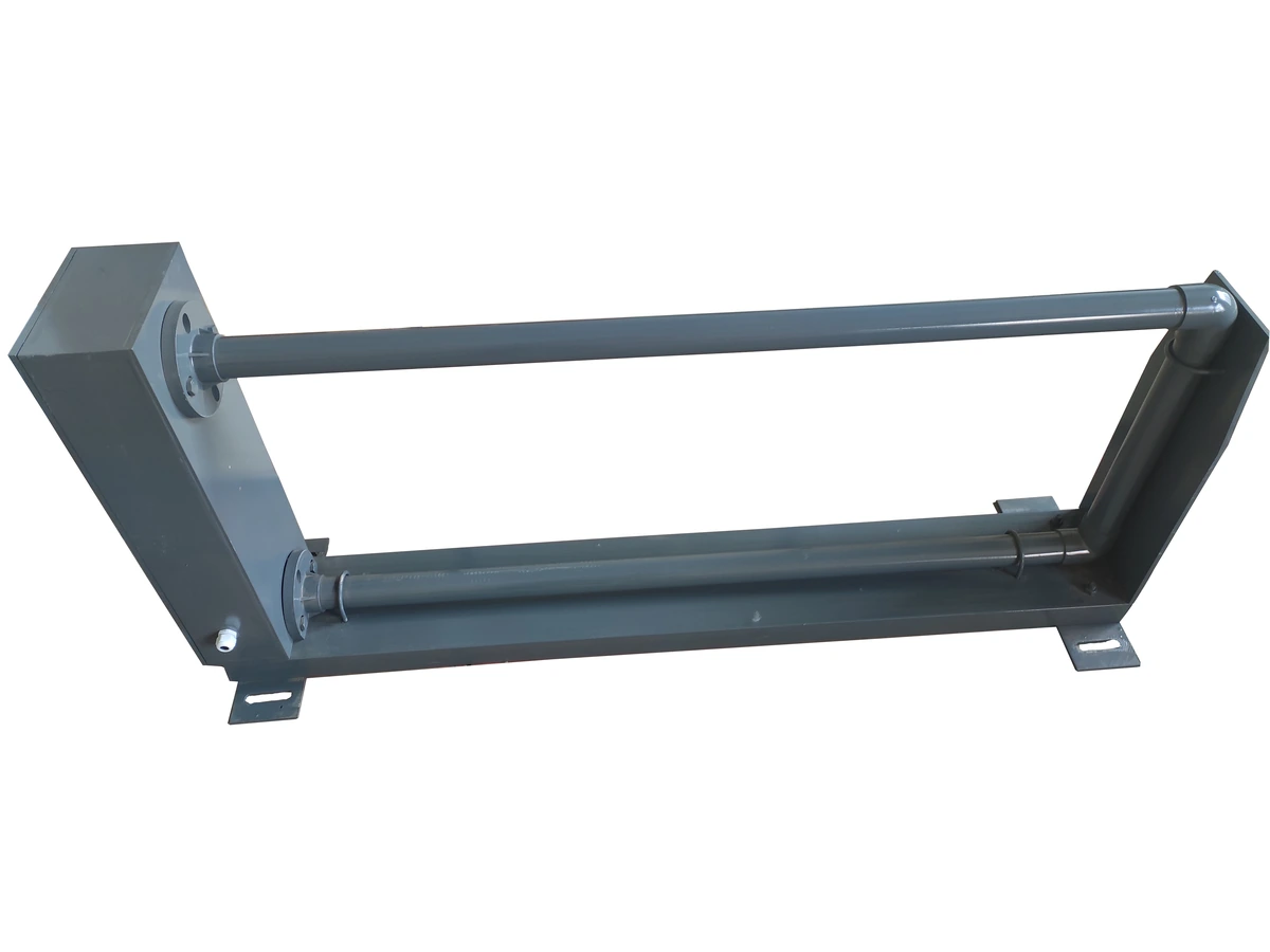
Check space to install the detector, space for safe operation, and space to remove it for service. An underbelt unit may avoid an overhead obstruction, yet still conflict with a return idler, cross-brace, steel deck, or cable route below the belt.
Mark those items on a side view and conveyor cross-section. Add the carrying belt, return belt, covers, chute, motor, and nearby magnetic equipment. Show where the sensor can enter during installation. A unit that fits its final position may still have no practical path into that position.
Does a frame always mean cutting the belt?
No. Belt cutting depends on the specific detector’s construction and installation sequence. Some frames split or open around an existing belt. A frame-style description alone does not establish that feature for the selected LJT-A. The conveyor metal detector range also includes a split-frame option when belt access is the main constraint.
Compare the actual assembly drawing with the available shutdown window. For either layout, include any approved support changes and a way to remove the sensor later. An underbelt installation can still require conveyor work.
How much steel must stay away from the sensor?
Use the selected detector’s metal-free-zone drawing; there is no single clearance for all underbelt or frame detectors. This is the area where nearby metal must be removed, restricted, or treated as the detector design requires. Moving steel and loose conductive joints can be especially troublesome.
The Eriez Metalarm 3500 QM2 installation manual, for example, treats surrounding steel, idlers, and cable routing as part of sensor installation. Its dimensions apply to that equipment. For your line, obtain the drawing for the detector being supplied before altering supports or covers.
What if the belt contains metal?
Identify steel cords, clips, and metal splices separately before choosing either layout. A periodic metal splice is different from steel reinforcement running through the belt. A belt-joint option does not automatically make a detector suitable for a steel-cord belt.
If splice handling temporarily suppresses detection, establish the length or time affected and test the target near the splice as well as away from it. Simply hiding a repeating splice alarm can leave an unexamined part of the belt. Send the belt specification and splice photos with the conveyor drawing.
How do you compare detection performance on your line?
Compare both candidates with the same target pieces, material conditions, belt speeds, and pass criteria. Record where each piece was placed, whether it was detected, and what the line did next. An empty-belt demonstration is useful for setup, but it cannot replace the loaded test.
METTLER TOLEDO’s metal detection guidance explains why target material, shape, orientation, aperture position, and actual operating conditions affect sensitivity. Apply those comparisons to your bulk load rather than borrowing a food-inspection sensitivity figure.
- Set the requirement. List the required targets, their materials and dimensions, and the alarm or removal action. Agree the number of repeat passes and acceptable unwanted-alarm behavior before comparing equipment.
- Map the target positions. Check left, center, and right across the working load. For underbelt detection, include positions near the belt and near the maximum load height. For a frame, include its identified weaker sensing positions within the opening.
- Run the relevant conditions. Include normal operation and the hardest normal combination of load depth, moisture, speed, and nearby operating equipment. Record those conditions rather than writing only “loaded test.”
- Keep a usable record. Use columns for target ID, position, orientation, material condition, speed, pass number, detection result, and line-response result. Record nuisance events during a defined run without inserted test pieces.
Use a planned test method that keeps hands out of moving equipment and allows every test piece to be recovered before it reaches a crusher or saleable stream. Isolate the conveyor before placing or retrieving pieces manually. Have the controls team manage live functional tests.
| Test result | What to do next |
|---|---|
| Underbelt detects all required positions with stable operation. | Keep it in the comparison; a surrounding frame is not automatically an improvement. |
| Underbelt detects near the belt but misses upper-load positions. | Review sensor clearance and load profile, then compare a frame or a different location using the same targets. |
| Either layout gives unstable alarms with no inserted target. | Investigate belt metal, loose supports, vibration, material changes, and electrical interference before changing sensitivity. |
| The detector alarms, but the target travels beyond the intended stopping or removal point. | Correct the control action, timing, or installation distance and repeat the complete test. |
Raising sensitivity alone may increase unwanted stops without fixing poor coverage. Change one suspected cause at a time, keep the required target unchanged, and repeat the failed positions after each change.
Will the line stop or reject in time?
Either detector needs enough distance and a working control connection for the chosen line action. A visible alarm proves detection occurred; it does not show that the belt stopped before the metal reached the protected machine.
Trace the complete sequence: target enters the sensing area, detector output changes, the line control receives it, and the belt or reject device acts. Compare that sequence with the output and wiring arrangement actually included in the quotation. The LJT-A or LJT-H name alone does not specify the complete interlock.
For stop-on-detect operation, have the controls team measure travel from the detection event until the loaded belt stops. Use a safely observed belt reference or position record, and include normal speed and loading variations. Compare the measured travel with the available distance to the first point where the metal would leave the controlled belt, such as a discharge into a chute. Do not count the extra distance from that discharge to a crusher as available stopping space. Allow for the site’s required margin and repeat the test after changes to speed, braking, controls, or detector position.
If the belt stops too late, the useful changes are an earlier detection point, a suitable change to the stopping system, or a different removal arrangement. Changing from underbelt to frame-type detection does not by itself shorten the conveyor’s stopping distance. For a timed reject or marker, test that the action follows the detected material at each operating speed, including after a stop and restart.
Which option costs less to install and run?
Compare the complete installed job. An underbelt detector can save work around an overhead obstruction, but required steelwork changes, controls, and downtime can reverse that advantage. There is no reliable price ranking from the layout names alone.
Ask for the same supply scope in both quotations: sensor, controller, mounting parts, cables, splice handling if needed, alarm or control outputs, commissioning, and the agreed test record. Separate items supplied with the detector from work your conveyor and electrical teams must perform.
Then add the site costs. Include access work, approved support changes, belt handling, production lost during installation, and later sensor removal. For operating cost, record unwanted stops and the time needed to locate and recover metal. A low purchase price is less useful if routine alarms repeatedly stop an otherwise productive line.
If the existing underbelt detector already passes the defined target test and runs steadily, keep it unless a changed requirement creates a gap. If a frame resolves a documented coverage problem, compare its installation cost with feasible changes to material presentation or detector location. Make that decision from the required result and measured operating conditions.
Which Corvelan detector should you compare first?
Compare our LJT-H first when an underbelt sensor offers the practical installation position and the target can be detected throughout the working load. Compare our LJT-A first when a surrounding frame fits and small targets or a high load make underbelt coverage difficult. Use the same target and operating conditions to settle any overlap.
An underbelt vs frame metal detector decision comes down to usable installation space, detection across the required load, and the line’s response afterward. Keep these three results separate in your comparison. A compact detector that misses the critical position is unsuitable; a detector that alarms reliably still needs the correct stop or removal action.
For a Corvelan recommendation, send the target metal and dimensions, belt width and profile, normal and maximum material depth, and a side photo or drawing of the proposed position. Add belt speed, belt and splice construction, and what should happen after detection. If some details are unknown, start with the photos and the metal you need to find; we can identify the remaining selection inputs.
Frequently asked questions
Can I keep an underbelt detector when production increases?
Yes, if it still passes the required detection and response tests at the new operating conditions. First identify how output increased. More material depth changes target distance; higher belt speed changes the response timing. Test the changed condition rather than replacing a detector solely because tonnes per hour increased.
Does a steel-cord belt rule out both layouts?
The layout name is not enough to accept or reject either detector. Ask for evidence that the proposed sensor and electronics can operate with your actual belt construction. Include a representative splice and target test. If compatibility cannot be established, review a suitable transfer point or belt arrangement before fixing the detector location.
Can either detector replace a magnetic separator?
Neither detector physically removes metal by itself. Keep magnetic separation when continuous removal of suitable ferrous metal is needed. Add detection when the task also includes a metal alarm, a line-control action, or targets that the magnet does not capture. The two devices can serve different parts of the same protection task.
Does the same tonnes-per-hour rating mean the same detector will work?
No. Equal throughput can produce different load heights and target positions. Belt width, speed, material bulk density, and loading pattern affect the cross-section of material passing the detector. Compare the measured load profile and the required metal target at the proposed location, alongside throughput.
What if the material is wet or highly mineralized?
Test the actual material condition before choosing the final detector. The material can change the background signal, and a different frame shape alone may not resolve that problem. Supply representative material information, including normal moisture changes, and compare target detection against the background at those conditions. If both candidates struggle, review the sensing technology and inspection position as well as the installation.