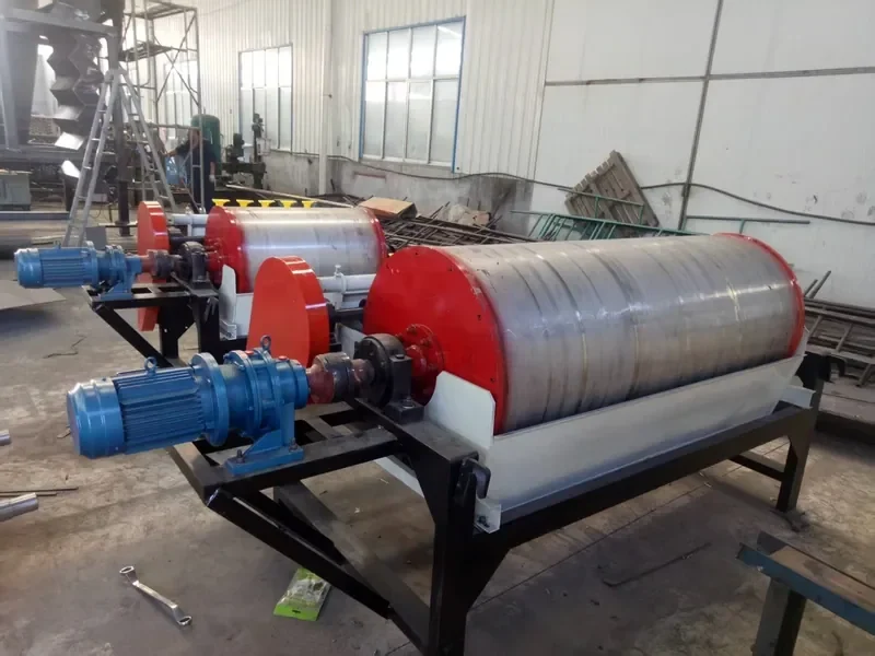
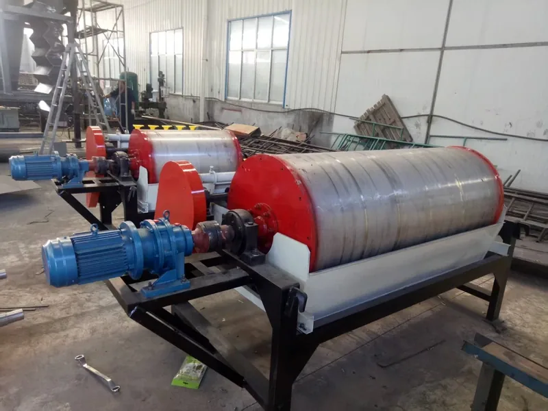
A wet drum separator recovers magnetite or ferrosilicon from dilute medium so it can return to a dense medium separation circuit. Effective wet drum separator medium recovery means keeping magnetic solids out of the waste stream while returning medium at a useful concentration and cleanliness.
Start with the loss location. If medium leaves on washed products, improve drainage and rinsing. If it leaves in the wet drum’s non-magnetic discharge, investigate the separator feed and recovery stage. Add another drum when the measured shortfall calls for it.
In this guide
- Where Does a Wet Drum Fit in a Dense Medium Circuit?
- Can the Same Wet Drum Recover Magnetite and Ferrosilicon?
- How Do You Measure Medium Loss and Recovery?
- What Should You Adjust Before Adding Another Drum?
- When Do You Need One Stage, Two Stages or Parallel Drums?
- How Should You Test and Specify a Medium-Recovery Separator?
- What Should You Send for a Wet Drum Recommendation?
- Frequently Asked Questions
Where Does a Wet Drum Fit in a Dense Medium Circuit?
The wet drum normally treats the dilute medium collected after product rinsing. It recovers the magnetic medium; the upstream dense medium vessel or cyclone separates the coal or ore by density. These are different jobs, even when both machines have “drum” in their names.
Magnetite or ferrosilicon powder suspended in water forms the dense medium. After density separation, some medium remains with both the light and heavy products. The plant needs to recover it for reuse.
Follow the drain and rinse streams
The typical sequence is:
- Drain: Screens remove much of the medium from the separated products. This stream can return to the correct-medium circuit—the suspension controlled for reuse in the vessel or cyclone.
- Rinse: Water washes remaining medium from the products. The resulting dilute medium goes to the recovery circuit.
- Recover: A stationary magnetic system inside the rotating wet drum captures magnetic solids. The shell carries them to a separate discharge; water and non-magnetic material leave through the other outlet.
- Return: Recovered medium joins the plant’s medium preparation system. Water and fresh-medium additions bring it back to the required condition.
The U.S. Bureau of Mines’ dense medium cyclone report, printed pages 3–4, describes this drain/rinse split. Some circuits also send a controlled portion of correct medium through magnetic separation to manage contamination. Follow the actual piping rather than assuming every stream takes the same path.
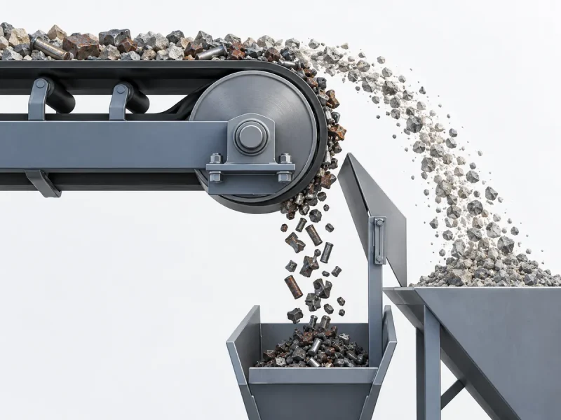
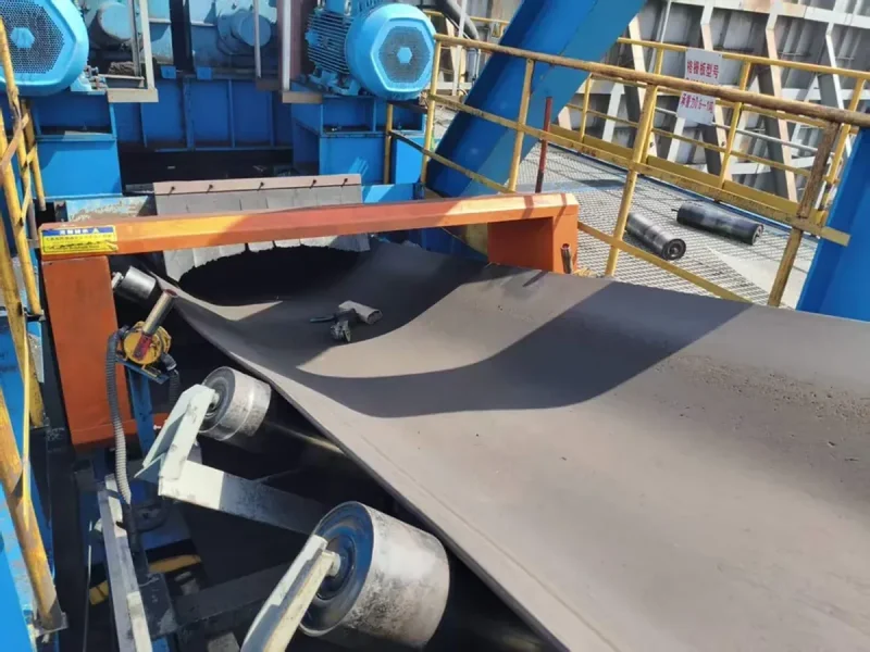
In a coal plant, this recovery duty is separate from removing steel bolts or rods above a conveyor. Our coal magnetic separator application page covers that conveyor protection task. A dry tramp-iron magnet does not replace wet medium recovery.
Can the Same Wet Drum Recover Magnetite and Ferrosilicon?
Wet drums can recover both magnetite and ferrosilicon, but a setup proven on one medium should be tested before using the other. Particle size, magnetic response, contamination and the amount of medium entering the drum affect the result.
| What changes? | Magnetite medium | Ferrosilicon medium |
|---|---|---|
| Common starting application | Dense medium coal washing | Mineral circuits needing a higher medium density |
| Material to identify | The actual magnetite grade and size distribution | The actual magnetic ferrosilicon powder grade and size distribution |
| Samples to compare | Fresh magnetite and circulating plant medium | Fresh FeSi and circulating plant medium |
| Result to measure | Medium lost, recovered-medium concentration and non-magnetic carryover | The same outputs, measured for the actual FeSi feed |
Ferrosilicon, often shortened to FeSi, is an iron–silicon alloy used here as a magnetic powder. It is not dissolved iron in water. Eriez’s wet drum brochure describes both magnetite and ferrosilicon as heavy-media recovery duties.
Test the circulating medium as well as fresh material. Fresh powder alone misses the fine coal, clay or mineral particles that accumulate during operation. ACARP’s Quality of Dense Medium project identifies particle size and the proportions of magnetic and non-magnetic solids as important to medium behavior.
If a medium change is planned, record the old and new particle-size distributions, magnetic fractions and operating density. Then compare wet drum losses and the returned medium under the intended flow. Changing the powder may also change the upstream suspension’s settling and flow behavior, so keep the density-separation result in the trial record.
How Do You Measure Medium Loss and Recovery?
Measure the magnetic medium mass leaving each loss stream, together with the flow through that stream. A tailings concentration alone cannot tell you the hourly loss or recovery percentage. Use the same sampling period for the feed and outputs.
First separate three possible destinations: medium carried away on products or rejects, medium discharged in wet drum tailings, and medium lost through spills or overflows. Fresh-medium consumption also changes when circuit inventory rises or falls.
For a circuit balance, use the same accounting boundary and dry-medium basis:
Unaccounted medium = opening inventory + additions − closing inventory − measured removals.
Count the medium held in the circuit’s tanks, sumps and equipment. Here, additions means powder dosed into the circuit, not deliveries to the warehouse. If inventory is rising after a restart, additions exceed actual loss. If inventory is falling, additions can understate loss. Investigate unexplained differences before attributing them to the drum.
Separate concentration, loss rate and recovery
| Measure | Calculation | What it tells you |
|---|---|---|
| Medium in a discharge | c, in grams of medium per liter of slurry | How concentrated that loss stream is |
| Medium loss rate | L = Q × c, with Q in m³/h and c in g/L | Kilograms of medium lost per hour; 1 g/L equals 1 kg/m³ |
| Loss per tonne processed | L ÷ dry plant-feed rate in t/h | kg of medium lost per dry tonne of plant feed |
| Recovery across the drum | 100 × recovered-medium mass rate ÷ incoming-medium mass rate | Percentage of the incoming medium collected in the magnetic product |
To obtain the incoming or recovered medium rate, measure that stream’s flow and medium concentration, then use the same Q × c calculation. If your records instead give slurry density and mass fractions, use medium kg/h = Q × slurry density in kg/m³ × solids mass fraction × magnetic-medium fraction of the dry solids. Enter 15% as 0.15, for example. Measure density from a representative slurry sample; do not substitute the density of water.
For several tailings branches, calculate Σ(Qᵢ × cᵢ). A grab sample from one outlet misses losses through another outlet or an overflow. Record whether “per tonne” means raw dry feed or saleable product; the two denominators give different numbers.
At steady operation, recovery can also be calculated as 100 × (1 − total medium loss rate ÷ incoming medium mass rate), provided all unrecovered-medium exits are included and medium is not building up inside the separator.
Ask the laboratory to report magnetic medium rather than total suspended solids. Coal fines and clay add to solids mass without being reusable medium. In an ore circuit containing natural magnetic minerals, magnetic mass may include more than the added medium; mineral or chemical analysis may be needed to separate the two.
A worked example: clearer water can hide the same loss
Suppose one wet drum receives 12,000 kg/h of magnetic medium. Its only loss outlet carries 120 m³/h of slurry containing 0.30 g/L of that medium. The plant processes 200 dry t/h.
- Medium lost: 120 × 0.30 = 36 kg/h.
- Drum recovery: 100 × (1 − 36 ÷ 12,000) = 99.70%.
- This outlet’s contribution to plant loss: 36 ÷ 200 = 0.18 kg/t.
Now suppose added water raises discharge flow to 180 m³/h and lowers concentration to 0.20 g/L. The loss is still 180 × 0.20 = 36 kg/h. The water looks cleaner, but the medium loss has not improved.
This is why a useful trial sheet puts flow beside every concentration result. Compare kg/h at matched conditions, then use kg/t to understand the effect on plant operation. Keep screen and spill losses separate from the wet drum result.
What Should You Adjust Before Adding Another Drum?
First stabilize the feed and identify whether loss comes from uneven distribution, excess liquid flow, excess magnetic load or a change in the medium. Adjusting drum settings while the feed keeps changing makes the results hard to interpret.
Read the symptom before changing the setting
| What you observe | First evidence to collect | Action and follow-up |
|---|---|---|
| Loss rises during flow peaks | Flow trend and paired tailings samples during normal and peak feed | Reduce surges or redistribute the load. Repeat the comparison at the same peak condition. |
| One side loses more medium | Feed-box condition and samples across the outlet width | Clear the distribution obstruction under safe isolation. Resample across the width after restoring even feed. |
| Loss rises after changing medium supply | Fresh/circulating powder size distributions and magnetic response | Compare the batches under matched flow. Resolve the material change before copying the previous settings. |
| Tailings loss is low but fresh-medium use stays high | Product/reject carryover, drain/rinse performance, spills and circuit inventory | Repair the identified loss path and repeat the stock balance. Another drum cannot recover medium that never reaches it. |
| Returned medium carries excessive non-magnetic solids | Feed contamination and magnetic-product solids composition | Investigate upstream fines entry and cleaning conditions. Compare recovered mass and returned-medium quality together. |
Use trends and paired samples to test a cause. For example, a loss increase that occurs only during a rinse-water surge points to a different first action from a loss increase that begins with a new powder batch.
Keep water flow, solids and magnetic load in balance
A wet drum has to pass liquid and transport captured magnetic solids. These are separate demands. Calculate both slurry flow per metre of useful drum width and magnetic-medium tonnes per hour per metre before comparing the load with the selected machine’s operating range.
Adding water can reduce a thick slurry’s resistance to flow and help release unwanted solids. It also raises the volume the tank must pass. Excess dilution can leave too few magnetic particles close together to form the clusters that help capture very fine medium. This interaction is discussed in Dworzanowski’s SAIMM paper on wet drum performance.
Keep each trial focused. Record feed flow, solids by mass, magnetic fraction of the dry solids, tank level and the settings actually changed. Change one controllable factor at a time where the process allows it, then compare medium loss and returned quality after the circuit settles.
Feed-box deposits, blocked outlets or backed-up launders—the channels carrying the products away—can change the flow through the tank. Inspect these before attributing poor capture to weak magnets. Eriez’s heavy-media operating instructions also treat water level and discharge arrangements as operating controls.
Isolate the drive and slurry feeds before clearing obstructions or making mechanical adjustments. A permanent magnetic field remains present when the motor is off; keep loose steel tools out of the magnetic zone. Use the selected machine’s adjustment procedure rather than borrowing another model’s gap, speed or magnetic-element position.
When Do You Need One Stage, Two Stages or Parallel Drums?
Keep one stage when it meets the agreed loss and returned-medium targets at normal and peak load. Use a second recovery stage for recoverable medium in the first stage’s tailings; use parallel capacity when excessive flow or load is the limiting problem. A second drum’s position determines what it can improve.
| Arrangement | Feed to the additional drum | Choose it to address |
|---|---|---|
| Single stage | No additional drum | Acceptable loss, concentration and cleanliness across the required operating range |
| Recovery stage, often called a scavenger | First-stage non-magnetic discharge, including relevant overflow branches | Magnetic medium still escaping after a stable first stage |
| Cleaning stage | First-stage magnetic product | Unwanted solids returning with the recovered medium |
| Parallel drums | Separate shares of incoming dilute medium | Hydraulic or magnetic loading beyond the available capacity |
In a series recovery arrangement, the second drum may still receive most of the water but only a small fraction of the original magnetic solids. Size and test it on that feed. Do not assume it will reproduce the first drum’s recovery percentage.
Tank flow also matters. Eriez’s heavy-media descriptions distinguish concurrent flow, which can produce a clean magnetic product, from counter-rotation designs with a scavenging zone. Multotec’s Permax product likewise uses a specific counter-rotation tank. Compare the actual flow drawing and test results rather than selecting from a model suffix alone.
Calculate what a scavenger must recover
If the second stage treats all first-stage tailings, and both magnetic products count as recovered medium:
Combined recovery = 1 − (1 − first-stage recovery) × (1 − second-stage recovery).
Use fractions in this equation. Suppose the earlier 12,000 kg/h example has a first-stage recovery of 0.997, and a trial shows that a scavenger recovers 0.80 of the medium remaining in its feed.
- First-stage loss: 36 kg/h.
- Additional medium recovered: 36 × 0.80 = 28.8 kg/h.
- Final loss: 36 × 0.20 = 7.2 kg/h.
- Combined recovery: 1 − 0.003 × 0.20 = 0.9994, or 99.94%.
These inputs illustrate the calculation. In a real test, measure the scavenger feed and outputs. If only part of the first-stage tailings reaches it, include the bypass loss separately.
Decide where the second magnetic product goes. A stream carrying too much water or contamination may need to return through medium preparation or cleaning rather than directly to the correct-medium tank.
For an investment comparison, multiply the additional kilograms recovered per hour by expected operating hours and the actual delivered medium price per kilogram. Then subtract added power, water, maintenance and other running costs. Compare that net benefit with installed cost, including pipework, controls and the planned installation stop.
How Should You Test and Specify a Medium-Recovery Separator?
Test representative circulating medium at the required flow, and measure all magnetic-medium outputs as well as the quality of the returned stream. A strong recovery result at a reduced flow does not settle whether the machine can handle the plant’s peak condition.
Collect samples that can explain the result
Start with the process drawing and mark the wet drum feed, magnetic product, every non-magnetic outlet and any bypass. Include dilution and spray-water connections. A sample from a shared downstream sump may already contain other streams and can hide the drum’s own result.
For each test condition:
- Record the feed: Identify magnetite, FeSi or a blend. Measure slurry flow, solids percentage by mass, magnetic fraction of dry solids and particle-size distribution. Keep the fresh-medium batch identity with the circulating-medium sample.
- Record the operating state: Capture tank level, drum speed where available, water additions and feed variation. Allow the condition to settle before collecting the comparison samples.
- Take paired increments: Use suitable sampling points and collect repeated increments over the same operating window. Match inlet and outlet windows to the travel time through the circuit. Keep normal-load and peak-load samples separate.
- Measure both products: Determine medium mass rate in the magnetic product and in each loss outlet. Also measure returned-medium flow, solids concentration and non-magnetic content.
- Close the balance: Compare incoming medium with recovered medium plus measured losses, allowing for any inventory change. If the difference exceeds the agreed measurement uncertainty, investigate sampling, flow readings, settling or missed outlets before judging recovery.
Use an agreed laboratory separation method consistently. Rinse and recover fine material during sample handling so it is not lost before analysis. At low tailings concentrations, request a method with enough sensitivity to distinguish the acceptance limit; a result below a detection limit is not a measured zero.
Agree the acceptance conditions before ordering
| Define in the test or quotation | Make it specific |
|---|---|
| Feed envelope | Actual medium type, size distribution, contamination, normal/peak m³/h and magnetic kg/h |
| Medium loss | Named outlets, g/L together with flow, and the resulting kg/h limit |
| Recovery | Incoming-medium basis, included outputs, sampling period and treatment of inventory change |
| Returned medium | Required concentration and contamination limits suitable for the receiving circuit |
| Test quality | Sampling points, repeat measurements, instrument checks, laboratory method and acceptable balance uncertainty |
| Installation | Feed/discharge elevations, useful width, available space, wear conditions, power and service access |
Keep the signed test record with the sample results and instrument records. Repeat a representative condition after an adjustment to see whether the change persists. Independent laboratory analysis can help resolve a disputed magnetic fraction; calibrated flow measurements and a closed mass balance provide separate checks on the loss calculation.
Finally, observe how the returned medium behaves in the density-separation circuit. If low drum losses coincide with poor medium concentration or unstable separation, resolve that return-stream problem before accepting the overall recovery arrangement.
What Should You Send for a Wet Drum Recommendation?
Send the actual medium, flow range, loss measurements and a simple circuit drawing so we can relate the separator configuration to your recovery task. We review the slurry conditions, magnetic loading, tank arrangement and installation interfaces for our wet drum magnetic separator range.
Include these details in the message:
- Magnetite or FeSi grade, fresh and circulating sample information, and particle-size results.
- Normal and peak slurry flow, solids by mass and magnetic fraction of the solids.
- Each measured loss outlet, its flow and medium concentration, plus the current returned-medium quality.
- The proposed feed/discharge elevations, available space and the improvement needed.
Use the Corvelan contact form to send the figures and describe the drawing you have. We can then discuss the configuration and how to provide further project information.
Choose wet drum separator medium recovery around measured medium losses, usable returned medium and the real operating load. Stabilize and measure the existing stage first; select cleaning, extra recovery or more capacity according to the result.
Frequently Asked Questions
How can I estimate slurry flow if there is no flowmeter?
For a safely accessible stream that can be collected completely, measure volume over time: flow in m³/h = 3.6 × liters collected ÷ seconds. Collect several timed measurements under the same operating condition. Do not reach into moving equipment or open a pressurized slurry line to take a sample. For a large or inaccessible stream, arrange a suitable calibrated flow measurement; a pump’s nameplate maximum is not the actual flow through the wet drum.
Can I use total iron assay instead of magnetic-medium analysis?
No. Total iron can include material other than the recoverable medium. Magnetite, FeSi and iron-bearing contaminants do not have the same iron-to-medium mass relationship. Give the laboratory the fresh medium and circulating samples, and agree how it will measure the reusable magnetic fraction. Where the ore itself contains magnetic minerals, add the analysis needed to distinguish them from the added medium.
Can a wet drum recover a blend of magnetite and ferrosilicon?
Both components can respond to magnetic separation, but the blend must be tested as a blend. Compare its composition in the feed, magnetic product and tailings. High total magnetic recovery can still conceal preferential loss of one component, changing the medium returned to the circuit.
Is a quoted 99.9% recovery enough to choose a machine?
Only when the quoted feed conditions, test method and returned-medium quality match the task. Convert the remaining fraction into kg/h using your incoming medium rate. Then include losses elsewhere in the plant. A strong separator result does not resolve poor rinsing or spills outside its feed path.
What if the recovered medium is too dilute to return directly?
Measure the returned flow and solids concentration, then trace the water entering that stream. Adjust unnecessary water additions or the discharge arrangement where the design allows. If the required return concentration remains out of reach, assess a concentration step within the medium-preparation circuit. Repeatedly adding dry powder treats the density reading without correcting excess water.
Does demagnetizing the recovered medium mean throwing it away?
No. Demagnetizing reduces the residual magnetization that holds particles in clusters; the medium stays in the circuit. Where magnetic clustering prevents effective remixing, assess a suitable demagnetizing step before reuse. Its purpose is to redisperse the recovered solids, not remove their mass.
Should the returned medium contain zero non-magnetic solids?
Do not make zero contamination the default target. Control the medium for the stability, flow behavior and density separation the circuit needs. Non-magnetic fines can affect both stability and viscosity. Compare their proportion and particle size with the operating result, rather than maximizing cleaning alone. ACARP’s dense-medium quality work highlights this relationship.