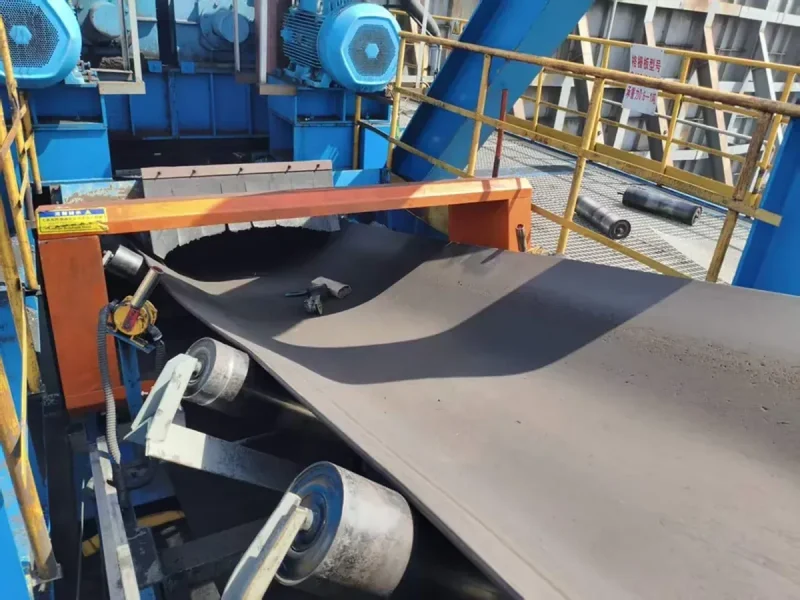
Conveyor metal detector sensitivity depends on the detector opening, the metal’s position in the load, and the signal produced by your material. Use the smallest opening that safely passes the loaded belt, then test the required metal at the hardest positions under normal and peak operating conditions.
For a tunnel detector, the center of the opening is usually less sensitive than areas near the coils. For an underbelt detector, metal near the top of a deep load is farther from the sensor. These layouts need different test positions. Start with the metal that could damage your crusher, mill, or other downstream equipment, then match the detector and feed arrangement to that target.
What does conveyor metal detector sensitivity mean?
Sensitivity describes the smallest specified metal target a detector can reliably find under stated conditions. A useful result names the metal, target size and shape, test position, material condition, and belt speed.
A setting of 8 or 80 on a control panel is a machine setting. It does not tell you the smallest detectable metal size. Even two detectors with the same setting scale can behave differently.
For repeatable comparisons, a test piece often contains a metal sphere of known diameter. A smaller detectable sphere of the same metal means better sensitivity when the other conditions match. A sphere avoids the direction changes that affect wire, strips, and other irregular shapes.
| Record with the result | Why it changes the comparison |
|---|---|
| Metal type and grade | A steel sphere and a stainless-steel sphere of the same size can produce different signals. |
| Sphere diameter or actual object dimensions | Wire diameter alone does not describe the signal from a long wire. |
| Position across and above the belt | A target near a coil can be easier to find than the same target elsewhere. |
| Opening and loaded material profile | Detector geometry and the metal’s path must match the proposed installation. |
| Material, speed, and working settings | An empty-belt result leaves out the material signal and production conditions. |
Keep the protection target separate from the test format. If the problem is a broken bolt or a manganese-steel tooth, include a representative object as well as any agreed spheres. A sphere test and an actual-object test answer different questions.
How does aperture size affect sensitivity?
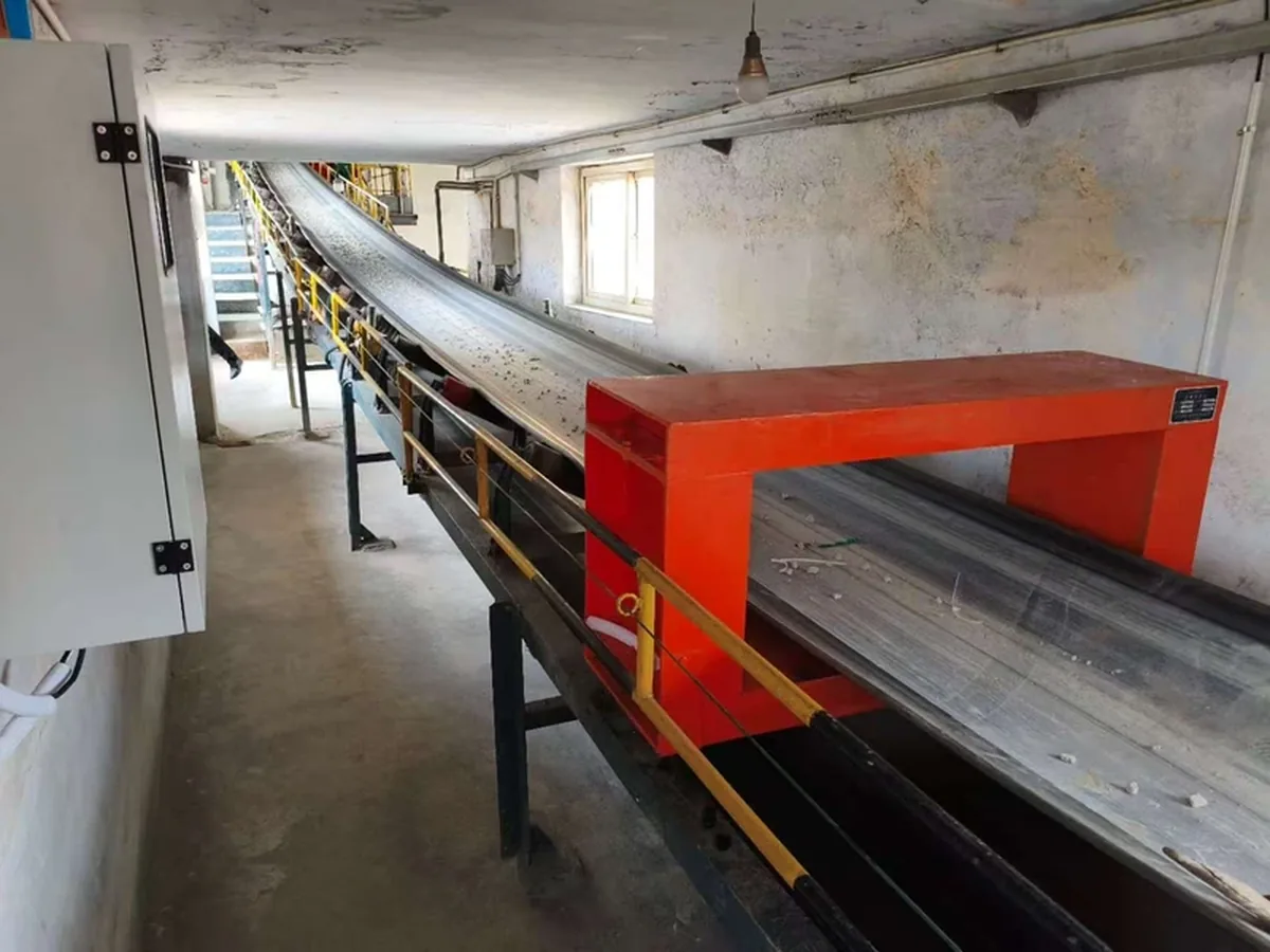
A smaller practical aperture usually improves small-metal detection, but it must still clear the belt, the largest normal load, and expected movement. Aperture means the clear opening through the detector, not the outside dimensions of its frame.
In a tunnel-style detector, enlarging the opening changes the sensing geometry. Aperture height often has a strong effect on sensitivity. Width matters too, so comparing height alone is not enough. There is no universal conversion from opening height to a detectable sphere diameter.
Measure the space the loaded belt actually needs
Use a conveyor cross-section to mark the carrying belt, trough shape, material profile, belt movement, and largest normal lumps. Include the highest normal load, rather than sizing the opening around a quiet period. Measure fixed dimensions while the conveyor is stopped and isolated; observe running load changes from a safe position.
- Width: allow for the full belt path and lateral movement, not just the narrow strip carrying material.
- Height: include the loaded profile, oversize pieces expected in normal operation, and movement of the belt and load.
- Mounting space: distinguish the clear opening from brackets, supports, and the outer frame.
Choose the clearances from the actual conveyor movement and the selected detector’s installation drawing. Excess empty height costs sensitivity; too little height lets material strike the head. Where occasional surges force a much taller opening, control the feed before deciding that the larger head is necessary.
Leave room around the sensing head as well
The opening is only one part of the installation. Nearby rollers, vibrating steelwork, and moving metal can disturb the field. The space that must remain clear of interfering metal is called the metal-free zone. Its dimensions depend on the head design and installation instructions.
Mark these limits on the layout before positioning supports or idlers. Keep the detector stable and route its sensing cables away from avoidable electrical interference. Improving this area can let you use a more sensitive working setup without repeated unwanted alarms.
Why does burden depth change detection performance?
A deeper material layer changes where metal can travel within the sensing field and can increase the material’s background signal. The harder test position depends on whether the detector surrounds the load or sits below the belt.
The depth of material on the carrying belt is called burden depth. It is not the same as aperture height. The opening also has to accommodate the belt profile and the mechanical clearances described above.
Tunnel and surrounding-frame detectors
For a conventional balanced-coil tunnel, the geometric center of the aperture is usually the least sensitive area. Metal near the belt surface may pass closer to a coil and give a stronger signal. A demonstration on an empty belt can therefore miss the difficult path inside a loaded stream.
Test the occupied load profile, including the center of the aperture if material can reach it. Do not assume that the top of the load is always the weakest point in every frame design. Use the selected head’s geometry and the actual metal paths to choose the positions.
Underbelt detectors
With a sensor below the belt, the upper part of the load puts metal farther from the sensing face. Include the gap beneath the belt and the belt thickness when finding that distance.
Suppose the sensor face is 60 mm below the belt’s carrying surface. With a 180 mm burden, a small target near the load surface is about 60 + 180 = 240 mm above the sensor. If the burden rises to 300 mm, that distance becomes 360 mm.
The distance has increased by 120 mm, or 50%. This tells you which target position needs another test. It does not give a percentage loss in sensitivity: that needs the sensor’s response and a test with the chosen metal.
If top-layer targets fail while lower targets pass, first see whether you can keep the feed shallower and more even. If the required tonnage needs the deeper load, compare a detector arrangement around the material stream and test it at that depth.
Material signal is a separate problem
Wet, conductive, or strongly mineralized material can change the background signal. A deeper or less uniform load can make that signal vary. The detector must distinguish the target from those changes. Product compensation and detector technology matter alongside distance.
Record the material condition with each test. If a detector works with dry feed but becomes unstable after rain, repeat the target test with the wetter feed after setting up for that condition. Reducing the alarm rate alone does not show that the required metal is still detected.
Throughput does not tell you the peak depth
You can use throughput to estimate the average loaded cross-sectional area:
Area (m²) = throughput (t/h) ÷ [3,600 × bulk density (t/m³) × belt speed (m/s)].
For a conveyor carrying 360 t/h at 2 m/s, with a bulk density of 1.5 t/m³, the area is 360 ÷ (3,600 × 1.5 × 2) ≈ 0.0333 m². Spread over an effective loaded width of 0.8 m, this equals a rectangular average depth of about 0.0417 m, or 41.7 mm.
A real troughed or heaped load has a higher local peak. Short feed surges can raise it further. Use this calculation to check the flow figures, then obtain the maximum loaded profile from the conveyor layout and safe observation of peak production. Size the opening and define the detection test from that profile.
How should you test sensitivity across a loaded belt?
Test known metal targets across the width and depth of the actual load, using the material, speed, and settings that production will use. Include the hardest expected position and verify the line’s response after detection.
- Define the target. List each metal that matters and its test size. Record the grade where known. Use identified spheres for comparisons and representative bolts, wire, or fragments for the actual damage risk.
- Set the operating conditions. Record the aperture or sensor layout, normal and maximum normal burden, material condition, belt speed, belt and splice type, and saved settings. Include significant speed or material changes in the trial.
- Map the target positions. Start with left, center, and right across the loaded width. At each, test near the bottom, within the middle, and near the top of the burden where those positions can occur. For a tunnel head, also cover its least sensitive occupied region.
- Control each pass. Use an approved nonmetallic test carrier or test arrangement that holds the target position and lets it be recovered. Place and retrieve samples with the conveyor stopped and isolated. Keep hands and loose objects away from the running belt, and prevent test pieces from reaching the protected machine.
- Repeat and record. Agree the number of passes and the acceptance rule before testing. Record detections out of attempted passes for each position, rather than a single combined pass rate. Keep unwanted alarms in a separate record.
- Follow the detected target. Verify the specified alarm, stop, marking, or reject action. Recover the target and identify the affected material. Detection at the head and successful isolation of the metal are separate results.
For wire or elongated fragments, repeat in different orientations: along the belt, across the belt, and upright where this can occur. Keep the length and cross-section in the record. Passing a steel sphere does not establish performance for a thin stainless-steel wire.
The Eriez Model 1235 installation and calibration manual illustrates why representative objects, burden height, and travel speed belong in a bulk-conveyor test. Use the calibration controls specified for the detector installed on your line.
Keep a result for every tested condition
Use one row per target, position, and operating condition. A practical record contains:
- Target identification, metal grade, dimensions, and orientation.
- Left/center/right position and height above the belt.
- Burden profile, material state, belt speed, and saved detector setup.
- Number of passes, number detected, and any unwanted alarms during a recorded running period.
- Alarm or control response, stopping or reject result, and sample recovery.
A miss in a required position means that condition needs correction and another test. Keep the individual result visible; successful passes elsewhere do not cancel it. If you change the detector setup, repeat the required target checks and the stability run with the revised settings.
What should you change when sensitivity is poor?
Find out whether the failure follows target position, material changes, belt movement, or the control response before changing sensitivity settings. The pattern tells you whether to improve the feed, installation, detector setup, or line layout.
| What you observe | What to compare first | Action and repeat test |
|---|---|---|
| Lower targets pass; upper targets fail on an underbelt installation | Sensor-to-target distance at peak burden, including the gap below the belt | Reduce unnecessary gap or stabilize a shallower feed. If capacity requires the deep load, trial a surrounding-frame arrangement. |
| Empty belt is stable; loaded belt gives unwanted alarms | Material condition and load profile when alarms occur | Set up for the actual feed and reduce surges. Retest the required metal after any compensation change. |
| Alarms recur once per belt revolution | Event timing against the splice, repairs, or material stuck to the belt | Identify the repeating cause. Review the belt/splice arrangement and test any splice-control function with the target. |
| Alarms follow a motor start or nearby machine movement | Event timing, vibration, cable routing, and nearby moving metal | Correct the installation disturbance, then run the target and clean-material stability checks again. |
| Metal triggers an alarm but reaches the crusher | Actual stopping distance or reject timing at loaded speed | Correct the response or detector position and retest the complete sequence. |
Do not lower sensitivity simply to make the alarm count look better. Equally, turning it up until the conveyor stops repeatedly is not a useful operating result. The working setup needs both reliable target detection and stable running with acceptable material.
Start by making the feed consistent and the mounting stable. Reduce unnecessary opening height where the approved layout allows it. Then set the detector for the real material and repeat the target tests.
If the required target still fails at the required depth and tonnage, change the arrangement being tested. Options include spreading the load, changing the sensing geometry, or using technology suited to the material’s electrical or magnetic response. Recheck the complete load profile after changing feed distribution: making one part shallower can move a peak elsewhere.
Which detector layout fits your burden depth?
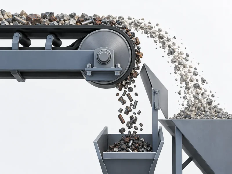
Start with a surrounding frame when the full load needs inspection and space allows; consider an underbelt sensor when access is limited and it can detect the required target throughout the load. For an existing conveyor, installation access may make a split frame the practical choice.
Our conveyor metal detector range includes different layouts for these situations. Match the mechanical arrangement first, then compare target detection under the same loaded conditions.
| Layout to consider | Where it fits | Sensitivity question to resolve |
|---|---|---|
| LJT-A conveyor metal detector | A bulk conveyor with room for a frame around the material path | Can the required metal be found across the occupied profile at maximum normal burden? |
| LJT-B split-frame tramp metal detector | An existing conveyor where installation without cutting the belt is important | Does the installed opening fit the load while the belt, splice, and nearby steel allow stable detection? |
| LJT-H underbelt conveyor metal detector | A location with limited space around the conveyor and useful access below it | Is the farthest required target still detectable with the deepest normal load? |
A split frame describes how the detector is installed. It does not, by itself, give a sensitivity ranking. Similarly, fitting an underbelt sensor into the available space is only useful if the upper load positions meet your detection requirement.
Set the target before choosing the detector
Improve conveyor metal detector sensitivity by controlling the opening, the loaded material profile, and the operating background together. Use the smallest safe opening, test the difficult occupied positions, and keep the required target detectable at peak normal production. A successful test also includes the line action that keeps the metal away from the protected equipment.
To discuss a Corvelan setup, send the material, target metal and dimensions, belt width, normal and maximum burden depth, and belt speed. Add the belt/splice type and a cross-section or installation photo. These details let us compare the LJT layouts and discuss the target test conditions with you.
Discuss Your Conveyor Detection Target
Use the contact form for the main details, or email drawings and target photos to [email protected].
Conveyor metal detector sensitivity FAQ
Can I size the aperture for the average load if large lumps appear only occasionally?
Include the largest lumps that must pass during normal operation. If they force an opening that is too large for your detection target, control or remove the oversize material before the detector. Keep required passages clear rather than planning routine contact with the sensing head.
Does a stainless-steel sphere test cover stainless-steel wire?
No. Add a wire sample with the relevant grade, diameter, and length. Test it in the orientations that can occur on the belt and at the difficult load positions. Do not convert the passed sphere diameter into a guaranteed wire diameter.
Do I need another test when the ore source or moisture changes?
Retest when the change alters the material signal or the load profile. Save the previous setup, record the new feed condition, and run both target checks and a stability run. Compare them before accepting the new working settings.
Can a belt-splice detector preserve detection around a metal joint?
Not automatically. Test the main detector’s response during and around the splice-control interval. Some splice functions suppress signals while the joint passes. The relevant question is whether your required target still triggers the intended action near that interval. Test with a controlled arrangement and plan how any uncovered interval will be handled.
Will increasing belt speed improve sensitivity by reducing burden depth?
It may reduce the average load area at unchanged throughput, but the faster belt also changes the detection and stopping conditions. Check the permitted speed range, peak load profile, and full target test at the proposed speed. Measure the resulting stopping or reject performance before changing the production setting.
One quotation gives a smaller test sphere at belt level. Is it the more sensitive detector?
Compare it with the other quotation at the same required positions first. Ask for the same metal grade, aperture, material, burden, speed, and test method. A belt-level result and an aperture-center result describe different paths and cannot establish a ranking on sphere size alone.