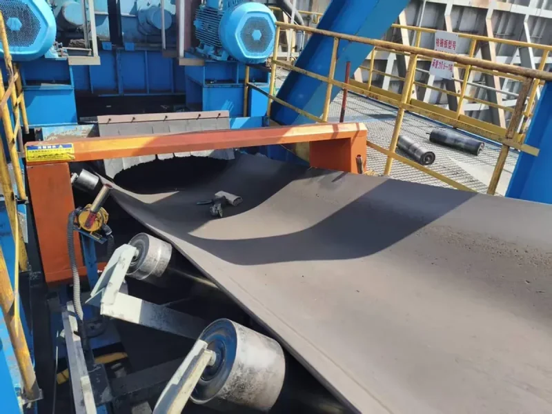
Conveyor metal detector installation should give the sensor a stable detection area and give the line enough time to stop or divert the affected material. Choose the location from both requirements. Then connect the metal signal to a defined action and test that action with the conveyor loaded.
A detector can report metal correctly while the object still reaches a crusher. The missing part may be stopping distance, a late diverter, an unrecorded speed change or a restart that releases material before anyone removes it. Start with the complete sequence: detect, act, isolate, then restart.
Where should you install a conveyor metal detector?
Install the detector upstream of the machine or transfer point you need to protect, with enough clear travel distance for the chosen response. Favor a stable conveyor section where material passes in a controlled layer and the sensing head is away from impact, moving steel and strong electrical interference.
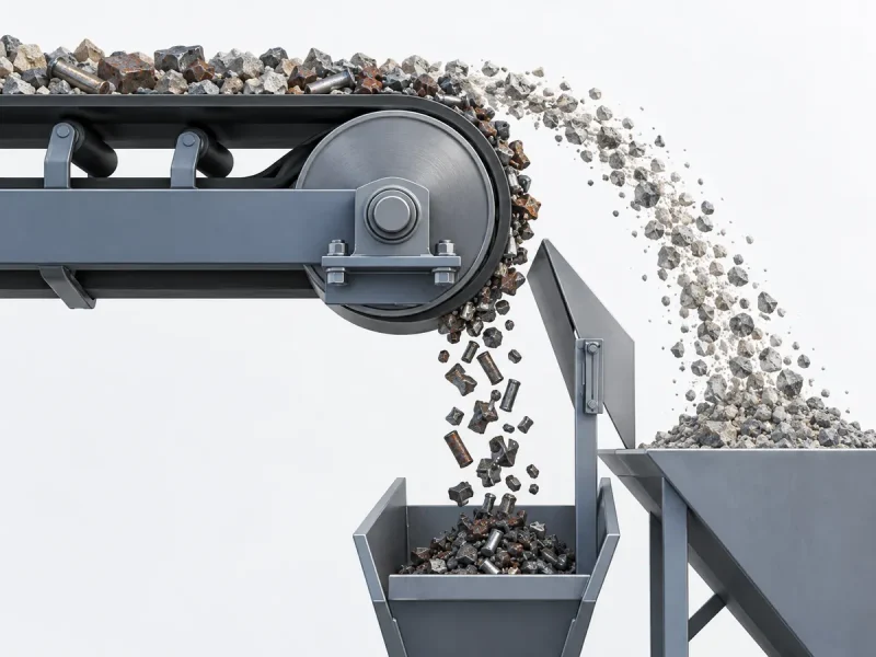
For a crusher feed belt, measure along the material path from the proposed detection reference to the point where metal can leave your control. That may be the head-pulley discharge, rather than the crusher inlet below it. Material already falling through a chute will keep moving after the belt stops.
The Eriez 1250-E1 installation manual makes this practical distinction: locate detection far enough ahead for the belt to stop, or allow for the diverter’s response at the conveyor speed. Use your own line measurements to turn that principle into a location.
Mark these items on a side view and conveyor cross-section before fabrication:
- Belt travel direction, width, trough profile and normal/maximum material depth.
- The sensing reference, nearby carrying and return idlers, support steel and guards.
- The protected discharge or reject point, with the available distance along the path.
- Motor drives, power cables, magnetic equipment and the proposed controller position.
- Safe access for tests, maintenance and removal of detected metal after isolation.
For a retrofit with too little stopping distance, move the sensing point upstream or redesign the response. A more sensitive setting will not make a coasting conveyor stop sooner. On a new line, reserve this space before placing chutes, support legs and cable trays.
How do you prepare the metal-free zone and mounting?
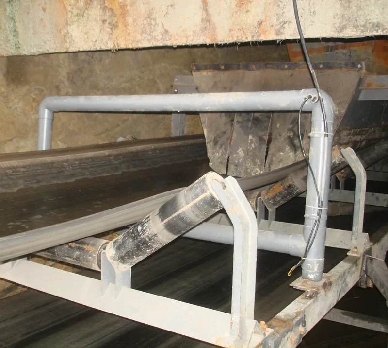
Use the selected detector’s installation drawing to set the metal-free zone, then build a support that keeps the loaded belt clear of the sensor. The metal-free zone is the space around the sensing area where unrelated metal must be excluded or controlled. For an aperture detector, it extends beyond the opening through which material passes.
Which nearby parts belong on the installation drawing?
Show fixed steel and moving metal separately, including parts below the carrying belt. Return rollers, rotating shafts, movable guards and reject mechanisms can be missed when a drawing shows only the upper belt. Include their full movement, not just their parked position.
The Eriez Xtreme reference guide explains that the sensing field extends beyond an aperture. It also describes false trips caused by changing electrical contact in nearby metalwork. This is why a loose bolted joint can matter even when no loose metal is being carried.
Get the required clearances for the actual sensing head and conveyor arrangement. A tunnel detector’s aperture-based spacing rule should not become a universal dimension for an underbelt or bulk-conveyor detector.
How should you support the belt and route cables?
Keep belt deflection, vibration and electrical noise out of the sensing installation. Allow for the belt’s lowest loaded position and its normal tracking movement. Where a slider bed is specified, use the approved material and supports; “plastic” alone does not establish suitable static behavior or stiffness.
Fit the supplied mounting and isolation parts without twisting the sensing head. Keep sensor cables apart from drive-power wiring, secure them against movement and protect them from falling material. Retain the supplied cable arrangement unless the manufacturer approves a change.
Mechanical isolation does not mean removing protective earth. Have the installer follow the selected unit’s earthing and shielding drawing. Adding random bonds or removing earth connections to cure false trips can create a different electrical problem.
What should the line do when metal is detected?
Choose an action that prevents the affected metal or material from continuing to the protected point. For occasional tramp metal on a bulk conveyor, a stop-and-remove arrangement is often the practical starting point if adequate stopping distance and safe access are available. For continuous operation, the line needs a suitable diverter and a contained reject route.
| Response | Where it can fit | What completes the job |
|---|---|---|
| Alarm only | An attended process where a later, defined action can still isolate the material | The operator or linked system acts before the affected material passes the control point |
| Belt stop | Occasional metal events on bulk belts | The belt stops in time, feeding is controlled, and metal is removed before restart |
| Marker plus stop | Metal is buried in material and hard to locate | The marked belt section remains accessible and the target is found and removed |
| Bulk-stream diversion | A continuous loose-material stream can be routed to a separate destination | The gate captures the affected interval and keeps it out of the normal discharge |
| Individual-product rejection | Separate packs or items have controlled spacing | The correct item leaves the line and enters the reject container |
A marker helps locate an event; it does not remove metal. Likewise, an air blast chosen for a light pack is not a sensible default for rocks or a deep bulk stream. Fortress’s reject-system guidance identifies product form, weight, shape, spacing and speed as selection factors. Match the mechanism to what must physically move.
Define the metal event, fault response and restart sequence
Write the event-to-action sequence before connecting the detector output to the line controls. A short output pulse may need to be latched in the PLC so the stop request remains active. A setting that holds an output after detection is different from a travel delay that waits before firing a reject.
For a stop-belt installation, agree on this sequence with the conveyor integrator:
- Record the metal event and request the designed belt stop.
- Stop or inhibit the upstream feeder as required to prevent a pileup.
- Keep the event active while the affected material is located and isolated.
- After safe removal and clearance, allow an authorized reset followed by a separate start command.
Also define the response to detector faults, a failed diverter and loss of required air pressure. A useful design holds material upstream or sends it to a controlled reject destination while protection is unavailable. Choose that state for the actual machinery and process; a normal metal-detection relay does not establish a personnel safety circuit.
The electrician needs the supplied output type, contact rating, normal/fault state, pulse or hold behavior and PLC input requirements. Use the proper interface to the conveyor controller rather than treating the detector contact as a motor-power switch.
How much stopping distance does the line need?
Allow for the travel before braking starts, the travel during stopping, and a margin based on measured variation. Use the worst relevant running condition, including the load and speed that produce the longest travel.
For an initial layout calculation, define:
- v: belt speed before deceleration, in m/s.
- t_r: time from the target crossing the agreed detection reference to the start of belt deceleration, in seconds. Include detector response, PLC processing and drive response in this interval.
- s_c: measured belt travel after deceleration starts until the belt rests, in metres.
- M: additional distance allowed for observed variation and the site’s design requirements, in metres.
Required distance = v × t_r + s_c + M
Suppose a conveyor runs at 2.0 m/s, the complete pre-deceleration response takes 0.30 s, and subsequent stopping travel is 2.4 m. For this layout exercise, suppose the project allows a further 0.6 m:
2.0 × 0.30 + 2.4 + 0.6 = 3.6 m.
If only 3.2 m is available before discharge, the proposed location is 0.4 m short of this example’s allowance. Move the detector upstream or develop and test a faster stopping or diversion arrangement. The 0.6 m used here is a stated example input; set the real allowance from the installation’s variation and consequences.
Obtain the response interval from a commissioning trace tied to the agreed sensing reference. Record the target’s reference crossing, detector output, stop command, deceleration start and final stopped position. A PLC log that begins at the output contact alone omits the detector’s earlier response interval.
If you measure the complete travel from the sensing reference to rest directly, do not add the same response travel again. Use that complete measured distance plus the chosen allowance. Repeat under relevant speed and loading conditions rather than using an empty-belt coast test as the only input.
This method assumes material follows the belt until stopping. On an incline or at a transfer, metal may roll, slide or continue falling. Arrange the detection point and isolation method around that extra movement; belt stopping distance alone then leaves part of the material path uncontrolled.
How do you set a metal detector reject device?
Match the reject mechanism to the material first, then set when it starts and how long it covers the affected material. A correct metal signal is only the starting event. The device must reach its effective reject position before the affected stream or item arrives.
Calculate the travel delay and actuator lead time
At constant material speed, start the reject command early enough to allow the full command-to-action delay. For a simple fixed-speed calculation:
Command delay = L ÷ v − t_a
Here, L is the remaining material-path distance from the target’s position when the timing event starts to the effective reject point, in metres. v is material speed along that path in m/s. t_a is the delay from issuing the reject command until the mechanism effectively diverts material, in seconds; include the relevant PLC, valve and actuator delays.
Suppose the target has 3.0 m left when the detector output starts the timer, moves at 1.5 m/s, and the command-to-diversion time is 0.20 s:
3.0 ÷ 1.5 − 0.20 = 1.80 s before issuing the command.
At 2.0 m/s, the same calculation gives 1.30 s. Leaving the delay at 1.80 s makes effective diversion start 0.50 s late; at that speed, the target travels another 1.0 m during the error.
Measure L from the actual timing event. If it begins at the detector output, the target may already be beyond the coil’s reference plane. Using the coil-to-gate distance without accounting for that movement makes the command late. If the calculation gives zero or a negative time, provide more travel distance or a faster response; entering zero does not cure insufficient time.
Cover the full reject window and speed changes
Keep the reject path active until the entire affected interval has passed. For continuous bulk material, allow for the uncertainty in target position, spread during transfer and gate opening/closing. For separate products, include item length, spacing, alignment and the mechanism’s recovery time. Test successive detections as well as isolated ones.
For example, a defined 0.9 m affected interval moving at 1.5 m/s takes 0.60 s to pass the reject point. The gate must provide effective diversion throughout that interval, with extra coverage for measured timing and position variation. The command’s hold time must also account for the mechanism’s opening and closing behavior; it is not automatically the same as that 0.60 s.
Where material changes speed or stops between detector and reject, use supported distance tracking or a suitable position-sensing arrangement. Fortress’s Stealth documentation describes encoder inputs for speed changes and reject timing. The selected detector/PLC must actually support the chosen arrangement. A speed setpoint alone does not measure belt travel, and belt travel may differ from material movement through a chute.
Distance tracking still needs actuator lead-time compensation. It also needs a defined response to lost pulses and a stop/restart with pending detections. Keep those events tracked or hold the affected material for controlled clearance; do not silently clear them when the belt restarts.
How do you commission the detector and line response together?
Run a controlled challenge from the sensing point to the final stop or reject destination, and record each part of the response. Agree on the target metal, its size and shape, the material conditions and the required result before starting.
Prepare a safe test method with the site team. Use identifiable, recoverable challenge pieces and a controlled collection arrangement so test metal cannot enter a crusher or be released with good product. Keep people clear of the moving belt and reject mechanism. Isolate electrical, pneumatic and other hazardous energy before manual retrieval or adjustment.
- Establish an empty-belt baseline. Run complete belt revolutions and observe the splice. Include normal starts, stops and nearby equipment operation. Log unwanted signals before changing sensitivity.
- Challenge detection under load. Use representative material and the difficult expected depth, target positions and orientations. Include the relevant minimum/maximum speeds. Record each pass and miss against the agreed target.
- Follow the metal event through the controls. Record detector indication, physical output, PLC receipt, stop/reject command and actual motion. Observe where the target and affected material finish. Test consecutive events and a stop/restart with an event still in transit.
- Prove the fault response. Have the commissioning engineer safely simulate the specified faults, such as unavailable detector power, loss of reject air or missing position feedback. The line should enter the agreed hold or reject state and retain a clear recovery path.
A reject cylinder reaching its limit switch does not establish that the target entered the reject container. Eriez describes reject confirmation as monitoring the reject device’s motion. Add the observation or sensing needed to establish actual separation for your application, including a usable reject chute and container.
Keep one test record that ties the result to the setup:
| Record | Detail that makes the result repeatable |
|---|---|
| Challenge | Metal type, dimensions, shape, identity, position and orientation |
| Production condition | Material, depth, moisture when relevant, loading and measured speed |
| Installation | Detector location, belt/splice, clearances and settings revision |
| Control sequence | Event/command times, stopping position or reject timing, feedback and reset behavior |
| Outcome | Detected or missed; target recovered from which location; affected material contained or released |
If detection passes but the target reaches the normal discharge, keep that trial as a failed line-response result. Adjust the responsible stage and repeat the challenge. Do not hide the failed isolation result inside a successful detector count.
What should you check when the installed system misbehaves?
Use the event pattern to find which part of the chain needs investigation. Separate a sensing problem from a control or material-handling problem before changing settings.
| What happens | Start here | What to repeat after the fix |
|---|---|---|
| Alarm repeats at the same belt position | Inspect the splice, clips and belt contamination during isolation | Complete belt revolutions, then the agreed target challenge |
| Trips coincide with a drive start or strong vibration | Compare event times with drive operation; inspect cable routing, mounting and nearby moving steel | The same operating sequence plus a target challenge |
| Empty belt is stable, loaded belt is not | Compare material condition, depth, belt sag and target position | The difficult loaded condition at the required speed |
| Detector indicates metal but the PLC sees no event | Trace the physical output, input state, pulse duration and input filtering | A complete event through the actual I/O chain |
| PLC receives the event but metal passes through | Measure stopping travel or reject timing; inspect actuator action and the actual material path | Recovery of the target from the intended stop/reject location |
These observations narrow the search; they do not establish a single root cause. For example, a drive-related trip may involve electrical noise, mechanical movement or both. Change the identified cause, keep a record of what changed, and repeat the affected challenge before restoring normal production.
Which Corvelan detector layout fits the installation?
Start with the conveyor geometry and installation access, then agree on the detection target and line response. We review the belt, material, surrounding structure and required action together. Four Corvelan layouts are relevant to this work:
| Your installation | Product to review | Detail to resolve first |
|---|---|---|
| Bulk conveyor with space for a frame around the material path | LJT-A conveyor metal detector | Conveyor cross-section, material depth and available response distance |
| Existing conveyor where opening the belt is undesirable | LJT-B split-frame tramp metal detector | Access to assemble the frame, belt/splice construction and surrounding steel |
| Bulk-material conveyor protecting downstream machinery | LJT-E conveyor metal detector | Target metal, frame fit, material conditions and the required control interface |
| Installation space mainly below the belt | LJT-H underbelt conveyor metal detector | Belt profile and target distance at the maximum material depth |
Both the LJT-B and LJT-E can be reviewed where cutting the belt is undesirable. Compare their mounting drawings and available access before choosing the arrangement. For every layout, specify the alarm, stop, marker or separate reject interface in the project scope.
Good conveyor metal detector installation connects a stable sensing position to a response that physically contains the metal. Set the clearances, calculate and measure the available response distance, then test the complete sequence under the intended running conditions.
To start a review, paste the material, target metal, belt width/profile, normal and maximum depth, speed range, available downstream distance and required action into Corvelan’s contact form. Mention any layout drawing or conveyor photos you can provide so we can arrange the file exchange. Also identify who will supply the conveyor controls, reject mechanism and commissioning work; those interfaces need one agreed sequence.
Conveyor metal detector installation FAQ
Does a split-frame detector eliminate the need for a metal-free zone?
No. A split frame helps you fit the detector around an existing belt; it does not remove the sensing head’s clearance requirements. Check the actual layout for idlers, steelwork and moving parts. The mechanical assembly method and the electromagnetic installation conditions solve different problems.
Can the detector sit beside an overband magnet?
Only after the two installations have been reviewed together. Show the magnet, its cleaning belt or discharge movement, power equipment and the proposed detector on one drawing. Establish spacing from the equipment-specific requirements, then test detection during the magnet’s normal operating and cleaning sequence. A fixed generic separation distance would miss differences between these arrangements.
Will a splice detector make any steel-cord belt suitable?
No. A splice option addresses a defined belt-joint event; it does not establish compatibility with metal distributed throughout a belt. Send the belt construction and actual joint details. Where a joint compensation mode is used, include target challenges at and near that joint so the operating window is covered by the acceptance test.
Should the conveyor continue when detector power is lost?
For a line that relies on metal detection, loss of detector power should trigger the agreed protection-unavailable response. The control system needs to distinguish a healthy detector with no metal event from an unavailable detector. After power returns, clear outstanding metal or reject events through the defined recovery sequence before releasing affected material.
When should installation tests be repeated?
Repeat the relevant tests after a change that can alter sensing or line response. Examples include a new splice, relocated supports or cables, changed belt speed, PLC edits, brake work and reject-valve replacement. Repeat detection after sensing changes and the complete isolation sequence after timing or motion changes. Keep the revised settings and results with the installation record.