When a metal detector is rejecting the wrong product, first trace package identification and reject timing. The detector may correctly find metal while a delayed command, lost pack reference, or slow reject device removes the pack ahead or behind it.
Start by following an identified challenge pack all the way into the reject collection point. Then separate a wrong detection signal from a wrong package selection and a failed physical ejection. This keeps the investigation focused on the part of the system that actually needs correction.
Jump to a troubleshooting step
What should you do when the wrong package is rejected?
Stop the affected product flow, keep suspect packs under control, and trace a known test pack through the complete reject sequence. Lowering sensitivity does not correct a reject device that targets the wrong package.
If a contaminated pack continues down the accepted line while a clean neighbor enters the reject bin, treat the event as a failed removal. For a food line, involve the person responsible for product safety. Use the last successful complete detection-and-rejection check, event history, and production records to establish the affected product. If the fault could have started earlier, widen the investigation rather than using the latest alarm as the start time.
Keep rejected and held product separate from saleable stock. A later passing machine test addresses the repaired setup; the held product still needs its own disposition decision.
For a controlled diagnostic run:
- Identify three representative packs: A is a normal pack, B contains a secured, identifiable metal test piece, and C is another normal pack. Keep all diagnostic packs out of saleable production.
- Run them in that order at a recorded speed and spacing. Use test-piece sizes and materials from the line’s approved test procedure. A loose metal fragment is not a suitable substitute.
- Observe the detector indication, reject command if available, actual device movement, and the route taken by each pack. Record whether B reaches the reject collection point and recover the test piece.
- Repeat the relevant failed condition after a correction. Change one setting at a time so that the result has a clear cause.
Observe from outside the guards. Before reaching into a pusher, flap, transfer, or belt area, isolate electrical power and stored pneumatic energy. Have a trained controls technician handle live signal tracing and control changes.
A photo of the rejected clean pack alone leaves the most important question unanswered: where did pack B go? Keep that identity visible throughout the investigation.
What does the reject pattern tell you?
Use the identity of the rejected pack and the conditions that cause the fault to choose the first check. A consistent one-pack offset points toward tracking or timing; a device that moves correctly but leaves the target behind points toward physical removal.
The following patterns are investigation starting points. Compare them with the recorded command and movement before deciding which component has failed.
| What you observe | First place to investigate | What separates the causes |
|---|---|---|
| A, the pack ahead of B, is rejected | Early command, wrong trigger reference, or wrong pack association | Did the output occur for A, or did an already extended device catch A? |
| C, the pack behind B, is rejected | Late command, slow actuation, or shifted product count | Was the command late, or did movement begin late after an on-time command? |
| B and a clean neighbor are both rejected | Reject duration, return time, spacing, or a deliberate group-reject setting | Was the device still active when the neighbor arrived, and was that behavior intended? |
| One isolated B passes the test, but a close sequence fails | Product registration, recovery time, or handling of queued detections | Did the controller retain both targets, and could the device complete both actions? |
| Failure begins after a speed change or restart | Fixed-time delay, speed feedback, or restart tracking | Does the recorded position still match the physical pack? |
| The device moves, but B continues or bounces back | Force, stroke, package control, or collection geometry | Does B leave the accepted path and remain in the collection area? |
| Alarms occur without B or repeat with each belt revolution | A separate detection-signal problem | Compare empty-belt behavior, belt position, normal product, and nearby machine operation. |
There are three different problems to separate. A false alarm is an unwanted detection response, perhaps from the product, belt, vibration, or electrical noise. Wrong-package rejection means the response is associated with the wrong physical pack. Failed ejection means the intended pack is selected but does not leave the accepted flow.
These problems can occur together. First demonstrate a correct detection of B and follow that event. If normal product also produces unwanted alarms, investigate that signal problem separately while keeping the required metal-detection performance intact.
Turning down sensitivity may reduce the alarm count while leaving the one-pack offset unchanged. It can also make a genuine test piece harder to detect. That is why we start with the pack sequence and the reject response.
How do you track one package from detection to the reject point?
Follow the same pack through registration, detection, command, movement, and collection. The alarm and the reject-bin count alone cannot show whether the correct pack was removed.
A sensor that sees the package edge, often called a photoeye or product registration sensor, gives the controller a pack reference. A belt encoder measures belt movement. A reject confirmation sensor detects a defined event, such as a pack entering the reject chute. A cylinder-position switch may report that the pusher moved. Each answers a different question.
METTLER TOLEDO’s metal detection guidance describes using sensors and encoders to target rejection independently of the metal’s position inside the pack. The important distinction is between identifying the package and detecting the metal somewhere within it. Metal near the leading edge reaches the detector before metal near the trailing edge. A timer started only by the metal signal can therefore shift its action within the package sequence. Registering the package gives the control system a reference that does not move with the contaminant.
Record the trigger, command and physical movement
For pack B, put these observations on one timeline:
- The package edge passing the registration sensor, if fitted.
- The detector’s metal indication.
- The control output commanding rejection.
- The device beginning its effective action on the product path.
- B arriving at that action point, then entering the collection area or continuing downstream.
A technician can use a controller trend to compare input and output transitions. A video taken safely from outside the guards can show package position and mechanism movement. Put a visible reference beside the conveyor, outside the sensing and moving areas, and use the same view for before-and-after comparisons.
If the output is late, investigate tracking and timing. If the output is on time but movement is late, investigate the actuator and its supply. A human reaction timed with a stopwatch can miss a short error; video frames or recorded signals give a more useful comparison.
Check the product sensor before changing timers
Pass known, counted packs through the sensor and compare the physical sequence with the controller’s registration input. Look for a missed edge, two registrations from one pack, or a beam that stays blocked between touching packs. Clear film, a loose wrapper, skewed packs, and a dirty or misaligned sensor are conditions to reproduce during this check.
Clean and align the sensor with the machine isolated where access requires it. Then repeat the input check with representative packaging. Have the technician correct sensing or input filtering based on the observed transitions; excessive filtering can merge closely spaced packs.
The controller may assign detections to a time or distance interval for each registered pack. This is its pack window. Compare the configured product length and sensor offset with the actual length in the direction of travel. A changed pack orientation or an incorrect window can assign a detection to the wrong unit.
Finally, establish what the confirmation sensor actually observes. A clean pack C entering the bin can produce a confirmation pulse even though B escaped. Match confirmation to the expected pack window and verify B’s physical destination during testing. Do not equate a pusher’s end-position signal with successful package capture.
How do belt speed and reject delay move the reject position?
At a steady speed, the travel time is distance divided by speed. A fixed delay becomes wrong when the speed, timing reference, or product movement changes.
Thermo Fisher’s Ten Tips to Assure Long-Term Success With a Metal Detector specifically calls for rejecter checks after a position or line-speed change. A detector can still find the test piece while its downstream response falls out of step.
Work from the actual timing reference
Find the event that starts the timer in the supplied control sequence. It may be a package edge at a photoeye, the detector output, or a tracked position. Measure the distance from that reference to the intended reject position along the product path. The front face of the detector housing is not automatically the timing reference.
For a simple example, suppose a selected pack edge must travel 0.80 m from a photoeye to its target position. The belt runs steadily at 30 m/min, or 0.50 m/s. The measured time from command to effective actuator movement is 0.10 s.
- Travel time: 0.80 ÷ 0.50 = 1.60 s.
- If this controller starts its delay at that photoeye edge and does not already compensate for actuator response, the starting command estimate is 1.60 − 0.10 = 1.50 s.
The purpose is to align effective movement with the chosen pack position. Some controllers already include response compensation or use distance rather than seconds. Read the timer definition before entering a value so that the same response allowance is not subtracted twice.
Now increase the steady belt speed to 45 m/min, or 0.75 m/s. Travel time becomes 0.80 ÷ 0.75 ≈ 1.07 s. If effective movement still occurs at 1.60 s, the pack edge has traveled 0.75 × 1.60 = 1.20 m—0.40 m beyond the intended point. At that moment a following pack may be in the reject zone instead.
This example explains a repeatable late rejection after a speed increase. Whether it misses one pack or more depends on the actual pack pitch and reject geometry.
Handle speed changes, stops and product slip
For variable-speed operation, use tracking that follows the actual travel between registration and rejection. An encoder can provide belt-distance information, but the control sequence must use it correctly. During acceleration, one speed reading divided into the distance does not describe the complete journey.
After a stop, determine whether pending targets are retained, paused, or cleared. Test restart with an identified challenge pack between the detector and reject point. If tracking is lost, keep those in-flight packs controlled and re-inspect them through the restored system before releasing the flow.
An encoder follows the belt, not a pack sliding on it. If downstream equipment stops and packs accumulate while the belt continues moving, the position calculation can become wrong even with an encoder. Fortress Technology describes this exact failure in its Reject Device Mistakes discussion.
Address the accumulation or transfer problem first: stop upstream flow before packs back into the inspection section, restore controlled spacing, and establish a defined recovery sequence. Adding an encoder alone will not resolve a pack that no longer moves with the belt.
How do package spacing and reject duration affect the next pack?
Reject delay decides when the action starts. Reject duration, sometimes called dwell, decides how long it remains active. Correcting one does not automatically correct the other.
If B is removed and C is also swept away, compare the end of the effective reject action with C’s arrival. The output may stay on too long, a pusher may return slowly, an air blast may spread across the gap, or the line may be set to reject a group deliberately.
Shorten the duration only when the evidence shows excess action. A pulse that is too short can touch B without moving it fully off the accepted path. Retest the package positions and weights that are hardest to remove after any change.
Compare package pitch with the complete reject cycle
Measure the package length in the direction of travel and the clear gap to the next package. Their sum is package pitch, measured from one leading edge to the next. Measure it at the reject section: a transfer or downstream backup can change the gap after the infeed sensor.
Suppose packs are 200 mm long, with a 100 mm clear gap, and move at 500 mm/s:
Pitch = 200 + 100 = 300 mm. Time between leading edges = 300 ÷ 500 = 0.60 s.
Now suppose the measured complete cycle for a pusher—from starting one action until it is ready to start another—is 0.65 s. It cannot complete two separate cycles 0.60 s apart. Moving the start delay does not make that mechanism recover faster.
At this example speed, 500 × 0.65 = 325 mm is the pitch needed merely to equal that measured cycle time. It leaves no allowance for variation and is not an accepted production gap. Use the mechanism’s supported operating range and sequence tests to establish the working spacing.
Choose the correction that addresses the limit: stabilize the infeed gap, reduce the required cycle rate, repair a slow return, or use a reject arrangement suited to the package and rate. Avoid repeatedly extending the reject window until it removes every neighbor.
Separate consecutive detections from one long reject
Run normal–challenge–normal, then challenge–challenge–normal sequences at the smallest approved gap. A single isolated challenge cannot reveal whether the controller can retain a second reject target or whether the mechanism can act again in time.
Some arrangements intentionally divert an entire affected group. That can be suitable when all suspect packs are captured and the associated product loss is accepted. Record the intended behavior before testing. Otherwise, rejecting two packs may hide a tracking error rather than solve it.
What if the command is correct but the package still stays on the belt?
Investigate the physical reject action when the command matches B’s arrival but B is not captured. More delay adjustment will not repair weak, slow, or obstructed movement.
Compare the command, actual mechanism movement, and package path separately:
- Movement starts late or varies between attempts. On a pneumatic device, record air pressure near the reject assembly during repeated actions, rather than relying only on a static compressor reading. A technician should compare supply capacity, valves, tubing, and flow controls with the specified setup. Inspect for a sticking or worn mechanism with energy isolated.
- Movement starts on time but B is only nudged. Compare the stroke, contact height, package weight, base friction, guide position, and the distance needed to leave the belt. An air blast or pusher that worked on a light carton may be unsuitable for a heavier or softer pack.
- B leaves the belt but returns to accepted flow. Trace its route through the chute or bin. Look for a full container, an obstructed opening, a hard rebound surface, or guides that direct the pack back toward the belt.
- The first reject works, later ones weaken or miss. Repeat the sequence while recording the return movement and air supply. This separates inadequate recovery or supply under repeated demand from a constant timing offset.
Restore the specified stroke, supply, and alignment before considering a different reject design. Raising pressure beyond the rated setting can create a guarding hazard or damage packages without correcting the trajectory.
Fortress Technology emphasizes matching the mechanism to package speed, spacing, size, and weight, and testing repeated rejects. Use those same conditions when comparing a repaired device with a replacement. A mechanism should remove the required packages cleanly and deliver them into controlled collection at the real production rate.
How do you prove the correct package is rejected every time?
Challenge the complete system with identified packs under the conditions it must handle. Record detection, correct pack selection, physical capture, and test-piece recovery separately.
An alarm is one result. B leaving the accepted stream is another. A confirmation input is useful only when it represents the intended event. Build the following checks into a written test plan with agreed pass criteria and repeat counts.
| Test condition | What to record | What a failure points toward |
|---|---|---|
| Test piece at the leading, middle, and trailing positions within the pack | Detection and the identity of the pack captured at each position | A dependence on where the metal is found, an incorrect pack window, or inadequate timing coverage |
| Required metal types and sizes at agreed difficult positions across the aperture | Each detection and complete reject result | Detection capability as well as reject performance; a missed detection cannot be repaired with reject timing |
| Minimum, normal, and maximum operating speeds | Actual speed and package route, including speed transitions where used | Incorrect fixed delay, speed feedback, or actuator response allowance |
| Normal–challenge–normal at the minimum approved gap | B captured; A and C follow the intended accepted or group-reject behavior | Excess duration, wrong association, uncontrolled spacing, or poor return |
| Two consecutive challenge packs followed by a normal pack | Both targets captured and every test piece recovered | Lost queued targets, cycle limits, or weak repeated actuation |
| A controlled stop and restart with a target in transit | Target position before stopping and its controlled destination afterward | Lost pending targets or a mismatch between tracking and actual travel |
Use representative product and packaging. Include the heaviest or most difficult pack where removal performance varies with the format. METTLER TOLEDO’s guidance calls for defined test-piece positions and checking both detection and reject timing; an easy position on an empty belt does not reproduce the full package task.
Where reject confirmation, low-air monitoring, or accumulation protection is fitted, have a trained technician test the intended fault response by the machine’s approved test method. Do this under controlled conditions with diagnostic product; do not defeat guards or create a blockage during saleable production. The recorded response should show how the line stops or contains product when the required removal cannot be confirmed.
For each run, retain the product and active settings, measured speed, gap, test-piece identity and position, observed output, actual captured pack, and the final destination of B. Keep failed results alongside the correction and repeat test. Do not replace the original failure with the later pass.
If B escapes even once in a test that requires B to be captured on every pass, the tested setup fails that criterion. Correct the fault and repeat the affected conditions, including the close sequence if timing, spacing, or return speed changed. Then obtain the line’s required restart approval and resolve held product separately.
When should you change the line setup or reject hardware?
Keep the existing equipment when corrected registration, timing, and handling pass the required sequence tests. Change the setup or hardware when a measured limit prevents reliable removal at the required rate.
If a product sensor misses packs, fix registration before adding a longer reject pulse. If speed varies, review distance tracking and the restart sequence. If packs accumulate or slide, correct product flow before relying on the encoder. If the actuator cannot recover or move the package reliably, address the mechanical limit rather than retuning the same delay.
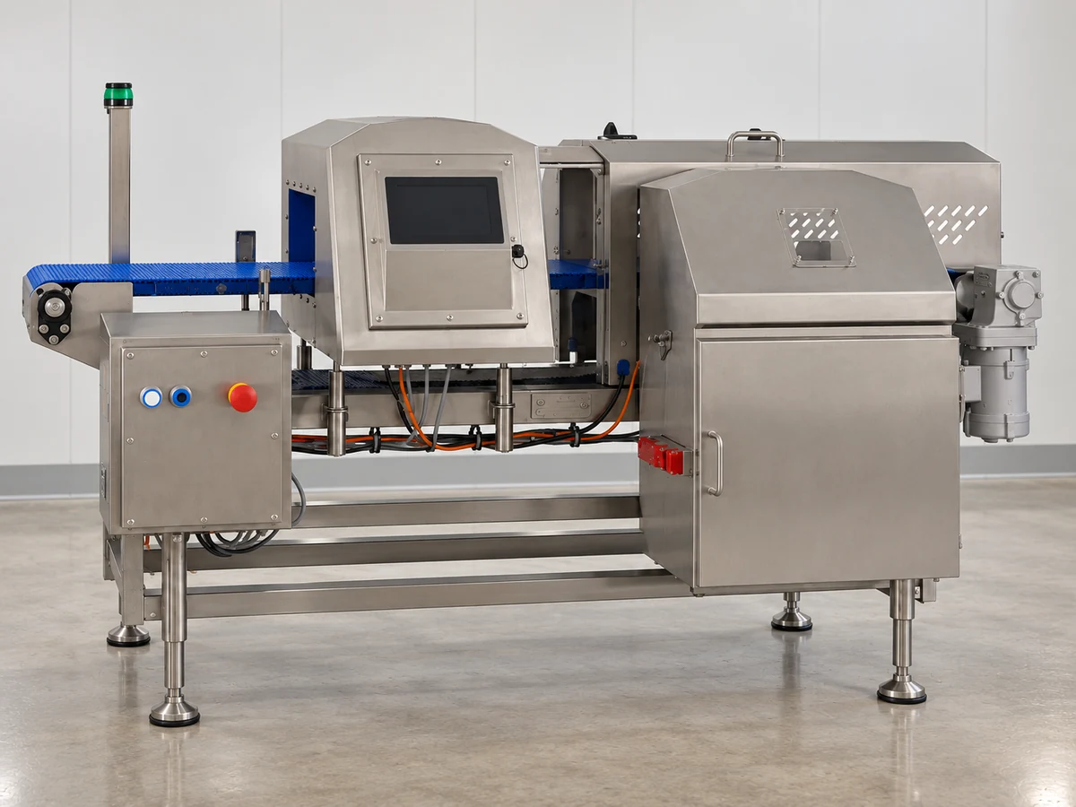
For packaged or unpackaged individual products passing through a detector opening, our LJT-F conveyor metal detector is the relevant product family to review. We consider product dimensions, packaging, target metal, belt speed, spacing, available reject distance, and the required response together. Automatic rejection is one response route; the final hardware and sequence are set for the project.
Put the product sensor, encoder, reject device, confirmation method, fault response, and restart behavior into the agreed technical scope. That makes the required integration clear before a line modification or new equipment order.
For a metal detector rejecting the wrong product, the deciding evidence is the journey of the identified target pack: it must be detected, selected, moved off the accepted line, and captured. A lower reject count alone is not the goal.
Need to review an LJT-F line configuration? Use our contact form to describe the product, package size and weight, measured speed and gap, reject type, and whether the pack ahead or behind is removed. Include the available detector-to-reject distance in the message. These details help us review the line response and identify what further layout or test information is needed.
Questions about wrong-package rejection
Why does a test wand work on an empty belt but fail with a package?
An empty-belt wand test does not reproduce package registration, product effect, or the physical removal of the pack. Use the actual product and packaging with an identifiable test piece secured at the positions required by the test plan. Record detection and capture separately. If the detector does not signal, investigate detection performance; if it signals but removes a neighbor, follow the pack-tracking and reject sequence.
Can a rejected package be released after one clean repeat pass?
A single repeat pass without an alarm is not enough to release a rejected pack. Keep it identified and controlled while the assigned quality person reviews the event. Product orientation, contamination position, or a different presentation can change the response. Use the site’s controlled examination or re-inspection procedure and record the disposition decision.
What if the problem started after washdown and the product counter jumps?
Start by comparing the product sensor’s actual input with the number of packs passing it. Water, dirt, changed alignment, or a moved bracket are conditions to investigate. Safely clean and restore the sensor, then watch whether one complete pack produces the expected registration sequence. If the input is correct but the count is wrong, have the technician inspect the controller’s input handling. If alarms also occur on an empty belt, investigate the detection signal separately.
Does one package causing two alarms mean two contaminated packages?
No. Two alarm events do not identify two separate packages. One pack can produce more than one response, and the controller must associate those events with the physical pack or group. Compare product registration with the alarm and reject records. Keep the pack under control until the event is resolved; do not use alarm totals as a count of contaminated units.
Can two product lanes share one reject device?
Only when the tracking and reject arrangement can control the affected lane or a defined group across both lanes. A detector event without lane identity cannot tell a lane-specific pusher which pack to remove. Review lane identification, overlapping arrival times, and the full reject coverage. If selective removal cannot be demonstrated, use a controlled group-reject arrangement or a separately tracked lane setup and test the combinations that can occur.