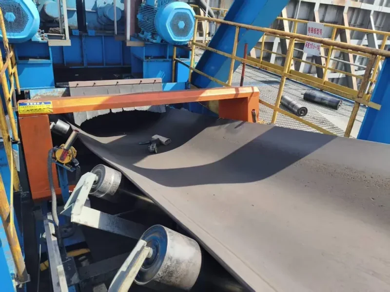
A useful conveyor metal detector test procedure checks known metal targets in real product, at defined positions and speeds, then proves that the line alarms, stops or rejects as required. An empty-belt alarm check is a starting check. Acceptance needs the product, the difficult positions and the complete response.
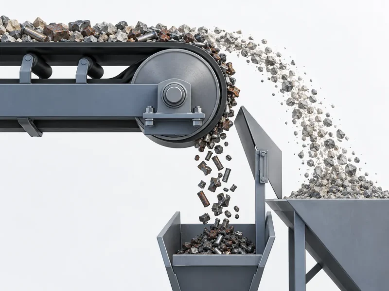
For a bulk conveyor, that means testing metal within the material load and keeping it away from the protected crusher or mill. For bags or individual products, it also means checking that the correct item leaves the good-product stream. Start with the job your line must perform, then build the test around it.
What should a conveyor metal detector test prove?
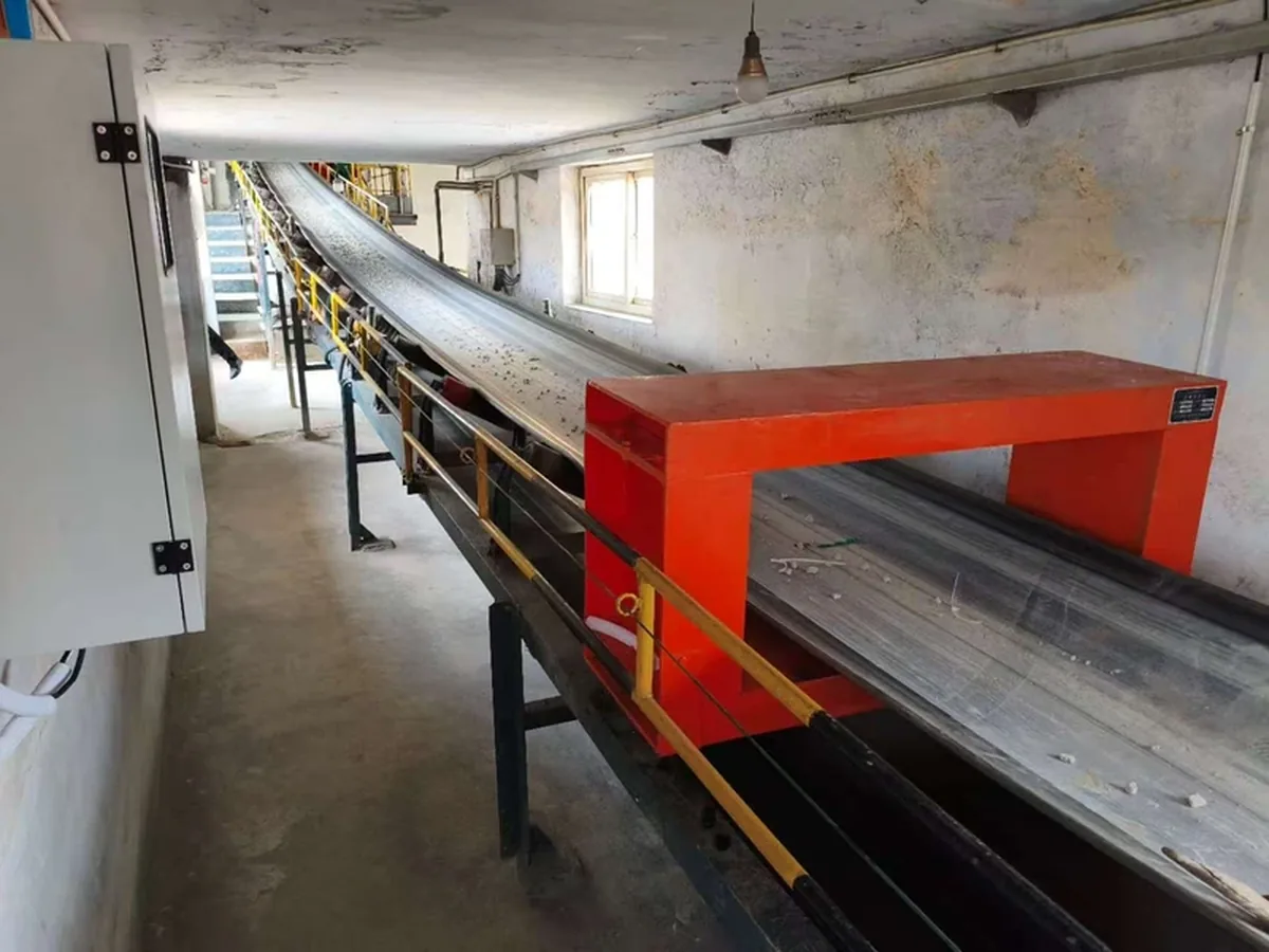
The test should prove that each required metal target is detected and that the specified line action works throughout the operating conditions being accepted. Write the pass conditions before running the test, so a convenient result does not become the acceptance rule afterward.
A factory acceptance test checks the supplied equipment and the conditions reproduced at the factory. A site acceptance test checks the installed conveyor, its surroundings and the connected controls. Routine checks then use a defined subset of those conditions to show that the accepted setup still works. A factory demonstration cannot complete a site stopping-distance check on a conveyor that is not present.
Before testing, put these items on the test sheet:
- The target: metal type or alloy, size, shape and any important orientation.
- The material or product: batch, packaging, temperature or moisture state, and normal and maximum permitted load depth.
- The conveyor: detector opening or sensor position, belt construction and splice, speed range, and product spacing where relevant.
- The test coverage: positions, operating conditions and planned passes per condition.
- The required result: detection, alarm, stop, marking or rejection, plus the acceptance rule for each installed fault response.
- The decision: who witnesses the test, who approves it, and how failures and retests are recorded.
Include a defined run without added test metal to assess unwanted trips. Specify its duration or product count and the allowed result in advance. A detector that finds the test piece but repeatedly stops normal production still needs work before acceptance.
Which product samples and metal test pieces should you use?
Use representative production material together with identified metal test pieces. Add the more difficult product conditions and actual contaminant shapes that could change the result. Keep the material sample and the metal target as separate entries on the record.
Choose product samples that represent the line
Take material from the process being inspected. Record the batch and measure the load depth at the detector, rather than using the feeder setting as a substitute. For packaged products, record the filled dimensions, weight, packaging and actual presentation on the belt.
Include normal production and relevant limits of the permitted process: deeper loads, uneven filling, wetter material, or a product at a different temperature. These conditions can affect the background signal, often called product effect. Do not flatten a lumpy test bag if normal bags reach the detector with that lump.
Anritsu’s technical note on product feeding and auto-setting shows why representative presentation matters. Hand feeding close to the head, condensation and changes in product thickness can change the learned signal. Learn or set up the product under its intended production conditions, then test that setup.
Group products only when the chosen samples cover the relevant differences. Similar names or recipes do not establish that the same setting works. A different bag thickness, fill level or packaging can require another test condition.
Use spheres and real contaminants for different jobs
Known-size spheres provide a repeatable sensitivity reference because a sphere has no different end-on or side-on orientation. Certified test pieces provide a record of the metal and its size. Check the identification against the certificate and inspect the carrier for damage before use.
Select the metals that the application must find:
- Ferrous metal: iron-containing targets such as an agreed steel sphere or machine fragment.
- Non-ferrous metal: name the material, such as brass or aluminum; do not record only “NFe” when the alloy matters.
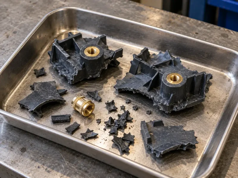
- Stainless steel or other special targets: identify the grade where known. Include manganese-steel parts if those are a real equipment-protection target.
Set the required size separately for each target. A ferrous-only protection task and an all-metal product-inspection task need different coverage.
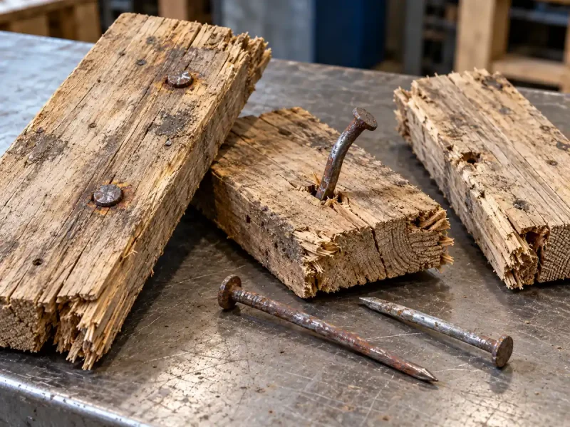
Add controlled trials with representative wire, flakes, bolts or other relevant shapes. Record wire diameter and length, or the dimensions of a fragment, and test meaningful orientations. A detected sphere does not establish detection of every irregular fragment with the same longest dimension. Keep the spherical reference and the actual-shape result on separate rows.
Where should you place the test pieces?
Test the positions where metal can actually travel, including the least sensitive accessible path for the detector design. Record both the position within the product and the position relative to the sensor. “In the middle” is too vague to reproduce.
Bulk material on a full-frame detector
For a conventional balanced-coil tunnel, the geometric center of the opening is commonly the least sensitive area. The METTLER TOLEDO sensitivity guide explains this center-of-aperture reference. A target passed close to the frame can give a stronger signal than the same target on a difficult central path.
Start by mapping the occupied cross-section of the load. A practical initial map can include left, center and right positions, with targets near the belt, within the middle of the load and near its top. Use only positions the material actually occupies, then add any difficult path identified during testing. This map is a way to find weak positions; it is not a fixed nine-point requirement for every detector.
Measure the target’s lateral position and height from a clear datum. Record the location of the metal inside its carrier, not just the carrier’s outer edge. A non-metallic holder can keep a target at a known depth, provided it is suitable for the line and does not change the material presentation being tested.
Underbelt detectors
With an underbelt sensor, give priority to targets farthest from the sensing element, including the upper part of the deepest permitted load. Include different positions across the belt because the belt profile and sensor shape affect the distance.
For example, a target lying on an empty belt is much closer to the sensor than one carried at the top of a deep load. Passing the first test is a reason to proceed to the loaded test, rather than accept the upper load untested. Use the installed sensor arrangement and the measured results to locate the difficult path.
Packs and bags
Check the target at the leading, middle and trailing parts of the product where required by the test plan. These are positions along the direction of travel. They challenge detection within the product and the timing needed to reject that product.
Also define the lateral path and target height through the opening. A target at the front of a bag can still be near the aperture wall; “leading” does not mean “least sensitive.” If a center position is required, prepare a controlled test pack or suitable fixture that actually places the target there. Mark its position so the next operator can repeat it.
How do you run the conveyor metal detector test procedure?
Run a controlled baseline first, then pass one identified target at a time with the material under the agreed conditions. Record detection and the physical line response separately. Keep the test settings unchanged while comparing positions.
- Prepare safe introduction and recovery points. Define how every test piece will be contained and recovered before it can reach a crusher, mill or saleable product. Use a suitable test collection or containment arrangement that keeps the target out of that equipment even if detection or stopping fails. Stop and isolate the conveyor before fitting holders or entering a guarded area. Keep people clear of the belt and reject mechanism during powered trials; do not attach a hand-held tether that could snag.
- Identify the installed setup. Record the detector ID, product program or settings, opening or sensor location, belt speed and control configuration. Check that the planned alarms and stop or reject equipment are available for the test.
- Run the empty belt without added metal. Observe belt joints and normal movement of nearby equipment. If alarms repeat at a belt joint or machinery cycle, resolve that interference before trying to qualify small targets.
- Run representative material without added test metal. Observe stability at the planned load and product conditions. If this run trips, investigate the material, possible real contamination and installation effects. Do not assume every trip is false.
- Run the first loaded challenge. Place the target in its defined position using the prepared safe method. Let the belt carry it through at the test speed, with hands clear of the head. Waving a test wand by hand changes the path and speed and may disturb the signal.
- Observe the complete event. Record the detector indication, the output received by the line controls and the resulting alarm, stop, mark or rejection. For an individual challenge, recover and identify the target before the next pass. For a planned sequence of challenge packs, account for every target at the end of that sequence before starting another test.
- Complete the matrix. Repeat each required metal, position, orientation and operating condition for the planned number of passes. For a stop-on-detect line, restore the documented test condition before each run. For continuous rejection, include the specified product spacing and speed conditions.
Use the normal production recipe or detector setting during acceptance. If a setting changes, record the change and repeat the tests that depend on it. A stronger target or easier position may help diagnose a problem, but it does not replace a failed required challenge.
How do you check the complete line response?
Follow the test target from the detector to its final controlled location. A detection signal is only one part of the result. Test the functions actually supplied and connected, using the approved control sequence as the expected result.
| Function being tested | What to observe | Acceptance check |
|---|---|---|
| Detection | Indication or event associated with each known target pass | The required target registers at every required position and condition in the plan. |
| Alarm | Local indication and any required remote alarm | The intended operator or control station receives the correct alarm. |
| Conveyor stop | Belt motion, material movement and final target location | The target stays within the defined recovery area and upstream of the protected hazard. |
| Marker | Mark placement relative to the target | The marked area contains the target within the agreed search window. |
| Automatic rejection | The actual challenged pack or material portion entering the reject area | The target is recovered in the controlled reject stream; other product is handled within the agreed reject window. |
| Reject confirmation | Sensor state, timing and actual target recovery | The installed confirmation function behaves as designed, and physical removal succeeds. |
| Fault response | Installed low-air, bin-full, detector-fault or other agreed inputs | Each selected fault produces the specified warning, stop or other controlled response. |
On a bulk conveyor, measure where the target finishes after the loaded belt stops. Include control delay and the belt’s real run-down behavior. Material can slide or continue moving after the drive receives a stop command. The stop output alone does not establish the final position.
On a pack line, run normal packs before and after a controlled challenge pack at the specified spacing. Check leading and trailing target positions as well as the middle. Where continuous running is required, include successive challenge packs to test whether the reject mechanism can recover and act again. Use the stated acceptable reject window when judging any neighboring packs removed with the challenge.
Be precise about reject confirmation. It may indicate that an actuator reached a position rather than that the contaminated pack entered the bin. The Eriez X8 reference guide, for example, describes a confirmation input using a switch at a pusher’s full extension. Observe physical target recovery as a separate check.
Qualified personnel should test fault inputs through the equipment’s approved simulation or commissioning method. Do not create an air failure by loosening a live connection or bypass guarding. Record uninstalled features as not applicable; a required feature that is absent remains an open acceptance item.
What counts as a pass, and what happens after a failed test?
Accept the setup only when every required test row meets its detection and response criteria, with failures resolved and the relevant retests completed. Keep an untested condition open rather than marking it passed.
Set the number of passes before testing. There is no single repeat count that covers every bulk conveyor, product-inspection system and customer requirement. Use the application risk, the applicable customer procedure and the agreed acceptance scope to choose the count.
For example, suppose a pack test plan calls for three metal types, three longitudinal positions and three repeat passes for each combination. That is 3 × 3 × 3 = 27 challenge passes for that product and operating condition. A second separately required speed condition adds another 27. Extra lateral or vertical positions add their own rows. These counts organize the work; a short successful series is not a measured guarantee of future detection probability.
When a test fails, keep the original result and separate the symptoms:
- Target missed: first verify its identity, actual path, speed, product state and selected settings. A displaced carrier can turn the intended test into a different one. If the setup is correct, investigate sensitivity, product effect and interference at that condition.
- Target detected, response wrong: follow the event through the output, line controller, timing, actuator and physical product movement. Changing detector sensitivity will not fix a pack that reaches the rejector at the wrong time.
- Normal material trips: establish whether there is real contamination, a material-related signal, belt interference or an installation problem before altering the threshold.
After correction, repeat the failed condition and other tests affected by the change. A shared sensitivity-setting change can affect all metal types and positions using that setting; a timing change affects the relevant speeds and product positions. Do not erase a miss by reporting only later successful passes.
If failure occurs during production, control the affected material or products and stop relying on the failed function until it has been restored. Use the site’s product-hold procedure to assess production since the last satisfactory check and authorize release after investigation.
What should the acceptance record include?
Record enough detail for another operator to repeat the challenge and reach the same pass-or-fail decision. Retain the individual results as well as the final signed decision.
At the top of the sheet, enter the line and detector IDs, test location, date, operator and witness, procedure revision, product or material batch, detector settings, aperture or sensor arrangement, belt and splice type, and connected response equipment. Add the planned speed, load-depth or pack-spacing conditions and the pass rules.
Use a separate row for each pass. The following fields can be copied into a spreadsheet or test sheet:
| Record field | What to enter |
|---|---|
| Test and pass ID | Unique row ID tied to the planned condition and repeat number |
| Material condition | Batch, measured depth or pack dimensions, moisture or temperature where relevant |
| Target identity | Test-piece ID, metal or alloy, sphere diameter or actual shape dimensions, certificate reference |
| Actual position | Lateral location, height or depth, leading/middle/trailing position and orientation where used |
| Running condition | Actual belt speed, product spacing and detector setting or program |
| Detection result | Pass/fail and the relevant indication or event-log entry |
| Line response | Alarm, stop location, mark or physical rejection result; fault test result where applicable |
| Recovery and action | Target accounted for, any failure, correction and linked retest IDs |
Attach the position sketch, settings record and any useful time-stamped event logs or video. For a stop test, retain the measured final target location. For a reject test, retain the target recovery result rather than relying only on a reject counter.
List the conditions covered by the final approval. Keep factory and site results identified separately. A later change in product, maximum depth, speed, detector position or control sequence calls for reviewing the affected coverage before using the old result.
How does the test change across Corvelan conveyor detectors?
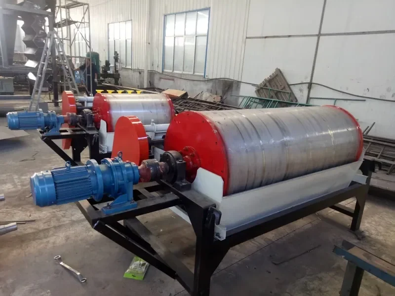
Match the test path to the detector arrangement, then check the line action specified for your project. Our conveyor metal detector range includes bulk-conveyor, product-inspection and underbelt arrangements.
| Detector | Test focus |
|---|---|
| LJT-A conveyor metal detector | Run the agreed tramp-metal targets within the actual bulk-material cross-section and check the connected protection response. |
| LJT-B tramp metal detector | For an existing conveyor using the split-frame arrangement, include the real belt, splice, nearby equipment and installed controls. |
| LJT-E conveyor metal detector | Define the relevant bulk-material targets and difficult loaded positions, then test the required alarm or linked action. |
| LJT-F conveyor metal detector | Test the actual product and packaging through the opening, including target positions and any supplied stop or reject arrangement. |
| LJT-H underbelt conveyor metal detector | Include the greatest target-to-sensor distance in the permitted load and the relevant paths across the belt. |
Agree the test targets and response hardware with the selected configuration. A model name or belt-width match does not set the minimum detectable metal size for your material.
An effective conveyor metal detector test procedure leaves a clear record: which target passed, where it traveled, under which conditions, and what the line actually did. Use the difficult loaded paths, account for every test piece and resolve failed detection or response checks before accepting the setup.
To discuss a Corvelan configuration, send us the material or product, target metal and dimensions, belt width, normal and maximum depth, speed and required response through our contact page. Include your existing acceptance procedure if you have one. Drawings and test-target details can also be emailed to [email protected] so we can review the conveyor fit and test requirement together.
Conveyor metal detector testing FAQ
Can one result cover the same recipe in different packages?
Only when the accepted test coverage includes the relevant package sizes, fill levels, materials and operating conditions. A taller or differently filled pack changes the target path and may change the product signal. Add a test condition for any relevant difference the original samples did not cover.
What if a sealed bag prevents placing a test piece at the center?
Use a dedicated test bag or a positioning method approved for that equipment when a center challenge is required. Identify and retain the test product so it cannot enter normal saleable stock. If you test only an outside surface, record that actual path; do not label it as a center test.
Can all metal test pieces pass through together to save time?
Test each metal independently for the sensitivity reference. With several targets together, a strong signal can hide a missed weaker target. Add close-spaced or multiple-contaminant challenges separately when the line must handle those events, and record their purpose and spacing.
Can the detector’s built-in self-test replace physical samples?
Only replace a specified physical test when the approved procedure accepts that method and its coverage. An electronic check may test parts of the detection system while leaving the actual product path or physical removal untested. Keep the required end-to-end response checks unless an accepted method covers them too.
What should happen if a test piece cannot be recovered?
Stop release of the affected test material and control every possible path until the piece is accounted for. Keep good-product and reject streams identified, investigate where it traveled and record the recovery. Do not resume testing with an unexplained missing piece in the line.
How often should the conveyor metal detector be tested?
Set the routine frequency from the application risk, customer requirements and the amount of product you could control after a failure. Establish the baseline at installation and review affected tests after significant equipment, product or setting changes. A convenient shift interval alone does not establish adequate coverage.