
High-Intensity Magnetic Filter for Fine Dry Powder
The NLD series uses an electromagnetic field and magnetic matrix to remove fine magnetic contamination from dry powder. Twin vibration motors help the powder pass through the matrix, while the PLC controls magnetizing, feeding, cleaning and iron discharge.
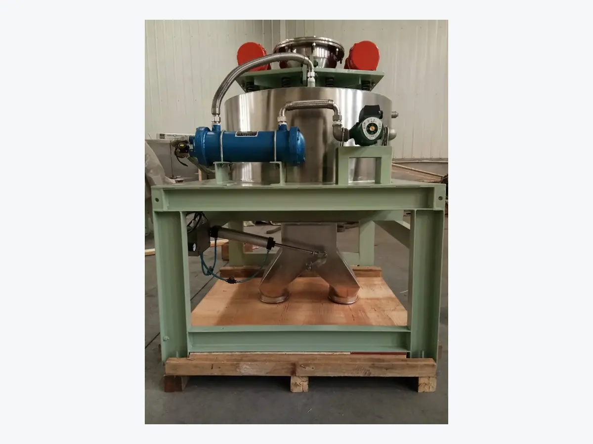
Is This the Right Filter for Your Powder?
Choose this dry electromagnetic filter when the product is a fine powder, the contamination responds to a magnet, and the powder can pass through the matrix without fast blockage.
Choose It
Use it for fine dry powder that needs stronger local magnetic capture than a simple open-gap magnet can provide.
Add a First Stage
If the feed contains a large amount of easy coarse magnetic material, remove that load first. Use the high-intensity filter for the finer fraction left behind.
Use Another Route
If the material is already a pumpable slurry, or if sticky powder quickly blocks narrow openings, this dry powder design is not the right first step.
When Is a High-Intensity Magnetic Filter Worth the Extra Complexity?
Use this equipment when fine or weakly magnetic contamination remains after simpler magnetic separation and that remaining contamination matters to product quality or downstream protection.
Use the NLD high-intensity filter
Choose it when fine dry powder needs more local magnetic capture than a simple grate, tube or other open-gap magnet can provide.
Add a primary magnetic stage first
If coarse or strongly magnetic material is present in high volume, remove that easy magnetic load before the fine matrix stage.
Do not add unnecessary complexity
If a simpler separator already reaches the result you need, use the simpler separator instead of adding a high-intensity matrix.
How This High-Intensity Magnetic Filter Works
The magnetic system captures contamination while energized, then releases the captured fraction after the feed stops and the magnetic field is switched off.
Energize the magnetic system
The electromagnetic system is switched on before the powder enters the active matrix.
Feed powder through the magnetized matrix
Fine powder passes through the matrix. Magnetic particles are attracted to the magnetized contact points.
Separated product leaves the product outlet
Material after magnetic separation continues through the filter and exits the product outlet.
Stop the feed and open the iron-discharge path
The feed is stopped before the cleaning stage begins.
De-energize and discharge the captured magnetic fraction
When the magnetic field is switched off, captured magnetic material can leave through the iron-discharge outlet.
What the Main Components Do
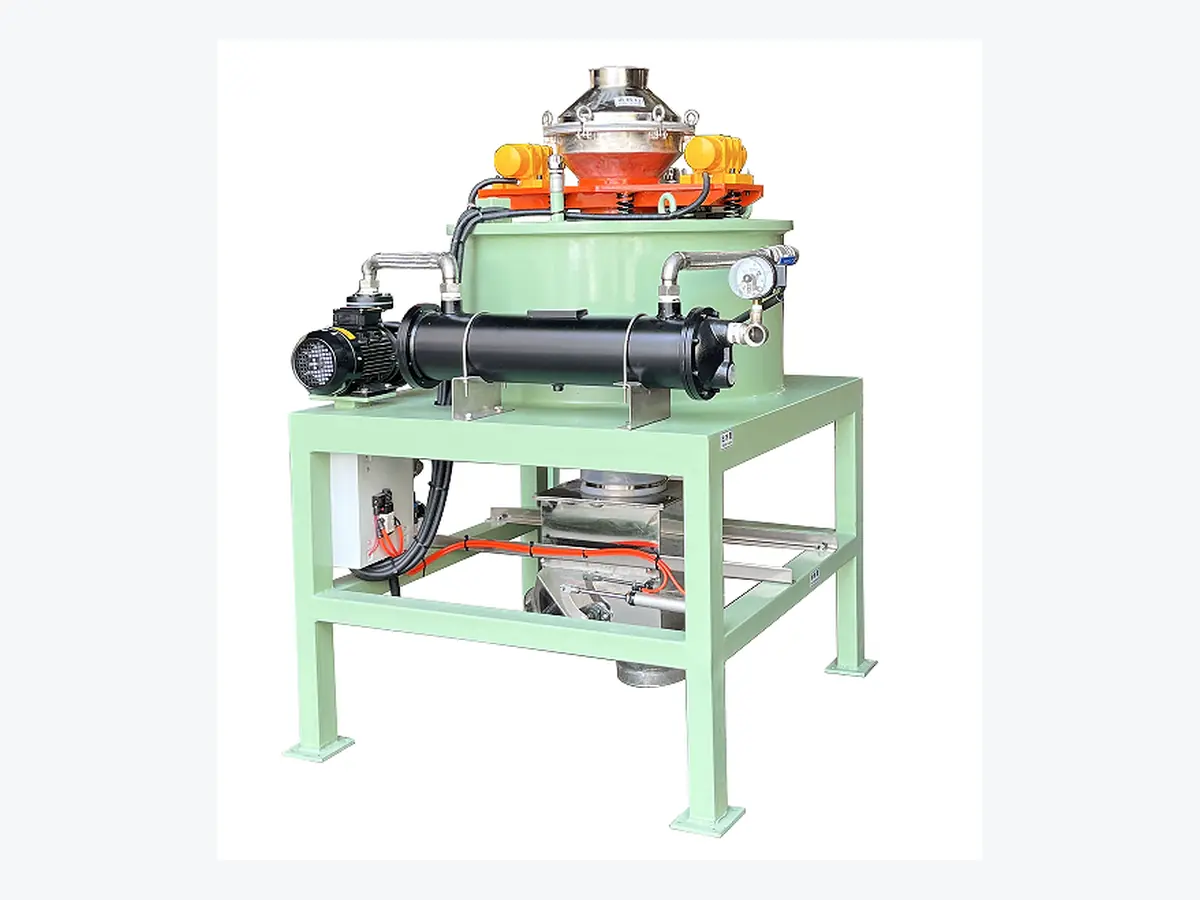
Twin vibration motors
Two vibration motors help fine powder move through the matrix instead of bridging above it. The vibration frequency can be adjusted to suit different powder-flow behavior.
Electromagnetic chamber and matrix
The chamber creates the magnetic field that magnetizes the internal matrix. The matrix provides many local capture points for fine magnetic contamination.
Cooling-water circuit
The water loop cools the electromagnetic system. It is separate from the powder path, so this remains a dry separation process.
PLC-controlled cleaning sequence
The PLC controls the operating stages, and the time for each stage can be adjusted to suit the material and cleaning cycle.
Why Vibration Matters
A strong magnetic field does not help if fine powder cannot enter and pass through the matrix evenly.
The twin vibration motors help keep the feed moving and reduce bridging above the magnetic section. For a free-flowing powder, this supports a more even presentation to the matrix. If the product cakes quickly, solve the flow problem before choosing a dense matrix.
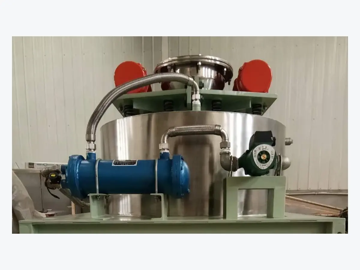
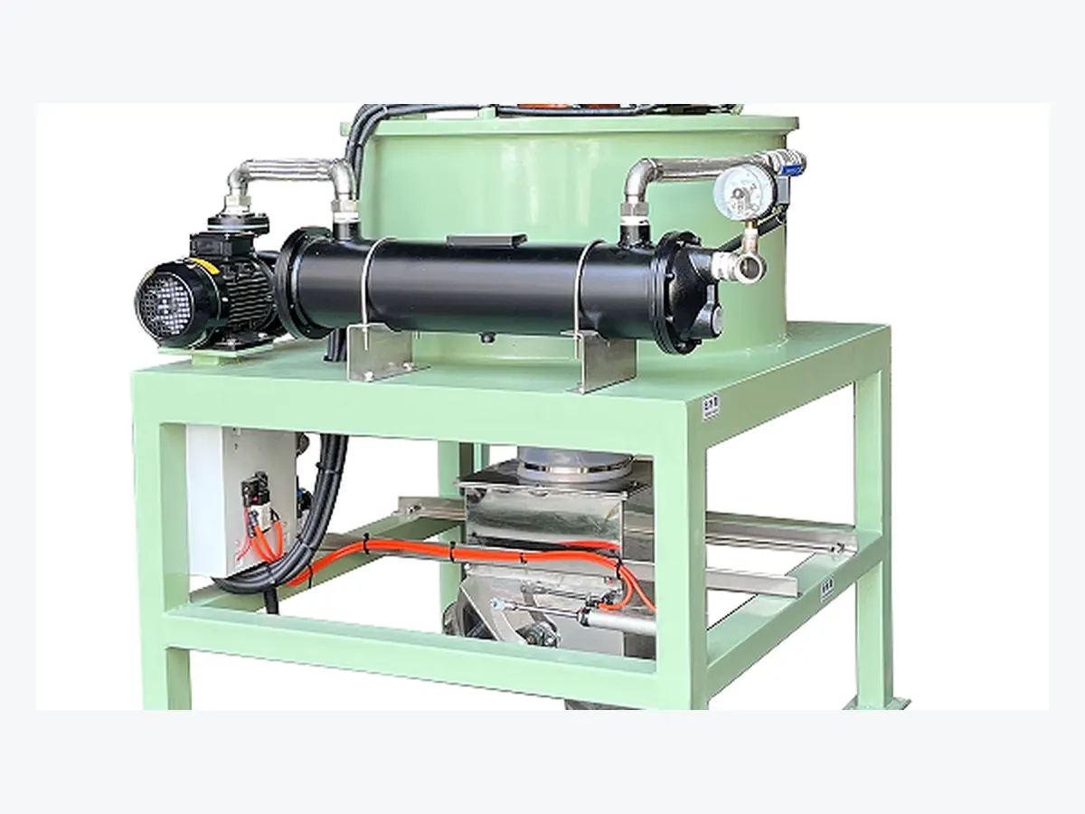
How the Electromagnetic System Is Cooled
The product uses a circulating water-cooling loop and monitors current and temperature to protect the electromagnetic coil.
The cooling water is for the magnetic system, not for the powder. Do not treat this model as a wet magnetic separator because it uses water for cooling.
High-Intensity Magnetic Filter Models
Use the reference throughput range to choose the first model to check, then confirm the choice against the real powder and required result.
| Model | Magnetic Field (GS) | AC Voltage (V) | DC Current (A) | Max Coil Power (kW) | Magnetic Chamber Dia. (mm) | Reference Throughput (t/h) | Dimensions (mm) | Weight (t) |
|---|---|---|---|---|---|---|---|---|
| NLD-A11K | 20,000 | 380 | 30 | 0–11 adjustable | 220 | 0.15–0.2 | 1230×1120×1726 | 1.8 |
| NLD-A15K | 20,000 | 380 | 52 | 0–15 adjustable | 250 | 0.2–0.3 | 1490×1300×1740 | 2.3 |
| NLD-A18K | 20,000 | 380 | 45 | 0–18 adjustable | 300 | 0.3–0.5 | 1350×1000×1673 | 2.6 |
| NLD-B25K | 20,000 | 380 | 80 | 0–25 adjustable | 600 | 2–4 | 1620×1970×1806 | 3.3 |
| NLD-B60 | 50,000 | 380 | 160 | 0–60 adjustable | 430 | 3–5 | 1980×2375×2424 | 10 |
| NLD-B60K | 40,000 | 380 | 160 | 0–60 adjustable | 600 | 4–6 | 2010×2525×2500 | 10.5 |
Reference throughput is product-sheet data, not a universal guarantee. Powder density, particle size, flowability, contamination loading, matrix condition and the final separation target can change the actual operating rate.
What Does the Magnetic Field Value Mean?
The model table reproduces the magnetic-field values in the current NLD specification. Before using a Gauss value as a purchase, factory acceptance test (FAT) or inspection limit, confirm exactly where and how that value is measured.
| Confirm Before Comparing Gauss | What Must Be Defined | Why It Matters |
|---|---|---|
| Measurement position | Chamber, matrix, matrix contact point or another defined location | Two values measured at different positions are not directly comparable. |
| Matrix condition | Matrix installed, removed, clean or loaded | The local field and gradient can change with the test setup. |
| Machine condition | Energized condition and operating state | The reading must be tied to one repeatable condition. |
| Instrument | Gauss meter and probe type | The measurement method should be repeatable during inspection. |
| Test point | Exact probe location and orientation | This allows the same point to be checked again during FAT or service. |
Which NLD Model Should You Start With?
Start with throughput, then use particle size, powder flow, contamination load and the result you need to confirm the model.
NLD-A11K
Start here when the reference throughput is around 0.15–0.2 t/h and a 220 mm magnetic chamber fits the process.
NLD-A15K
Start here for around 0.2–0.3 t/h. It uses a 250 mm magnetic chamber and an adjustable coil-power range up to 15 kW.
NLD-A18K
Start here for around 0.3–0.5 t/h when the 300 mm chamber and 18 kW maximum coil-power range fit the line.
NLD-B25K
Start here for the 2–4 t/h range. NLD-B25K uses a listed 600 mm magnetic chamber and a 20,000 GS model value.
NLD-B60
Start here for the 3–5 t/h range when the B60 dimensions, 430 mm listed chamber diameter and 50,000 GS model value match the process plan.
NLD-B60K
Start here for the 4–6 t/h range when the 600 mm chamber and B60K layout fit the installation.
What Materials Can This Filter Be Used For?
The NLD family is intended for fine dry powders where magnetic or weakly magnetic contamination must be separated from the product.
Battery & Fine Material Powders
Manganese dioxide, carbon, lithium manganate, lithium cobalt oxide, ternary materials and other fine battery-material powders listed for this equipment family.
Magnetic Mineral Particles
Hematite, limonite, siderite, chromite and manganese-bearing mineral particles are listed among the fine-particle applications.
Non-Metallic Mineral Iron Removal
Feldspar, quartz and kaolin are listed for fine-particle iron removal. Wolframite and monazite also appear in the application list.
Material name alone does not prove the final result. Two powders with the same name can behave differently because particle size, magnetic behavior, moisture, contamination loading and flowability are different.
Check Powder Safety Before Equipment Selection
A powder can be suitable for magnetic separation without being suitable for a standard electrical installation.
Ordinary non-hazardous powder
Continue with normal model, installation, electrical and dust-control checks.
Combustible or easily ignited dust
Do not use the standard product page as proof of explosion-protected suitability. Send the material safety information and site hazardous-area classification before equipment selection.
ATEX, IECEx or other certified area
Do not assume compliance from the product name or application list. The exact certification, equipment scope and installation requirements must be confirmed before quotation.
What We Confirm Before the Filter Is Released for Installation
The model can be correct and still be difficult to install if the feed, outlets, service space or support structure are not checked before production.
| Installation Item | What We Confirm | Why It Matters |
|---|---|---|
| Feed inlet | Size, connection type and upstream feed arrangement | The powder must enter the unit without unstable surging or restriction. |
| Product outlet | Size, direction and downstream connection | A restricted outlet can cause powder backup and unstable flow. |
| Iron-discharge outlet | Size and captured-material collection arrangement | Removed magnetic material needs a controlled discharge path. |
| Overall envelope | Selected NLD dimensions and available site space | Prevents interference with nearby equipment and structures. |
| Support / foundation | Model weight, mounting points and support method | The support must carry the equipment and vibration safely. |
| Service clearance | Top and side access for matrix, motors, cooling and discharge components | Maintenance must remain possible after installation. |
| Feed control | Gravity feed or controlled feeding, depending on the upstream process | Large flow swings can change buildup on the matrix and separation stability. |
| Dust connection | Whether the process requires enclosed venting or dust collection | Fine powder should not be released around the machine during normal operation or cleaning. |
What Utilities Must Be Confirmed Before Order?
The current NLD table confirms 380 V and model-specific DC current and coil-power ranges. Phase, frequency, control voltage and cooling requirements still need to be locked for the destination site.
| Utility | Current Public Information | Confirm Before Production |
|---|---|---|
| Main electrical supply | 380 V listed in the NLD model table | Phase and frequency for the destination factory |
| Coil power | Adjustable maximum power listed by model | Total connected load including motors and control system |
| Control system | PLC-controlled operating and cleaning sequence | Control voltage, required signals and plant-control interface |
| Grounding / cable entry | Not defined on this public page | Local electrical standard and final cabinet layout |
| Cooling-water circuit | Circulating water cools the electromagnetic system | Flow, inlet temperature, pressure, connection size and water condition for the selected model |
| Temperature / cooling protection | Current and temperature monitoring are part of the supplied product description | Exact alarm and shutdown logic for the final control design |
If the site is 380 V
Start with the standard electrical basis, then confirm phase, frequency and the control-system requirements.
If the site is 400 / 415 / 480 V
Do not assume direct compatibility. Send the site voltage and frequency so the electrical design can be confirmed before order.
If plant PLC integration is required
Define the run, stop, alarm, cleaning-status and protection signals that the plant needs before the control scope is frozen.
What Controls Cleaning Frequency and Daily Maintenance?
Cleaning frequency is driven mainly by contamination loading, throughput and how quickly the matrix fills. A higher magnetic field does not remove the need for the right cleaning cycle.
| Operating Condition | Start With | Why |
|---|---|---|
| Low magnetic contamination | Longer run between cleaning stages | The matrix loads more slowly. |
| Medium contamination | Shorter timed cleaning cycle | Clean before buildup starts to reduce separation stability. |
| Heavy coarse magnetic load | Primary magnetic separator before the NLD filter | Do not solve a bulk-load problem only by cleaning the fine matrix more often. |
| Sticky or bridging powder | Improve powder flow before relying on the cleaning cycle | PLC timing cannot fix blocked powder flow. |
| Dust-sensitive process | Contained iron collection and cleaning arrangement | Captured contamination and fine powder should remain controlled. |
What needs regular inspection?
Vibration motors
Check mounting, abnormal vibration, bearing noise and cable condition.
Cooling system
Check flow, leakage, operating temperature, pump condition and heat-transfer cleanliness.
Magnetic matrix
Check buildup, blockage, damage and whether the matrix can be cleaned and serviced as intended.
Iron discharge
Check valve condition, captured-material buildup and whether discharge remains clear.
Electrical / PLC
Review alarms, current and temperature conditions and investigate abnormal changes.
Maintenance interval
Set the interval from actual operating conditions and component instructions. Do not use one generic hour value for every powder.
Why the Matrix Matters More Than a Gauss Number Alone
The matrix turns the magnetic field into many local capture points, but those points only work when powder can reach them and the matrix has not become overloaded.
The specified magnetic field at the matrix contact point exceeds 16,000 Gauss. Confirm the measurement method for the quoted unit. This is a local matrix-contact reading, not proof of a guaranteed removal rate or product purity.
Fine weakly magnetic target
Use enough local capture opportunity so small particles meet a strong magnetic gradient.
Heavy contamination load
Remove the easy magnetic fraction first. Do not use fine matrix capacity to hold large amounts of coarse material.
Sticky or poor-flow powder
Do not force sticky powder through a dense matrix. Improve flow or use a more open design first.
How We Check the Actual Powder Before Finalizing the Model
A model table gives the starting point. The final model should be tied to the real powder, one recorded test setup and one agreed way to judge the result.
Record the feed
Record the material, particle-size range, moisture, bulk density, magnetic contamination, normal throughput and peak throughput.
Define the result you need
State what must improve: lower iron content, fewer visible magnetic particles, better mineral purity, better downstream protection or another measurable result.
Record the test setup
Record the test machine, NLD model, magnetic setting, matrix, feed rate, vibration condition and cleaning cycle used during the test.
Take defined samples
Keep a feed sample, a separated-product sample and the captured magnetic fraction where the test method requires them.
Use the same test method before and after
Do not compare a laboratory result before separation with a visual check after separation. Use the same agreed method and sampling basis.
Compare the result with the required limit
The result should be judged against an agreed limit, not against a Gauss number or the amount of material stuck to the matrix.
Information we record during a test
| Test Record | Recorded Value |
|---|---|
| Sample ID | Record for the actual sample |
| Material | Product name / grade |
| Particle-size range | Range or D10 / D50 / D90 if available |
| Moisture / bulk density | Actual test condition |
| What must be removed | Fine iron / weakly magnetic fraction / other magnetic target |
| Test machine / model | Record the unit used |
| Magnetic setting / matrix | Record the actual setup |
| Feed rate / test duration | Record the operating condition |
| Cleaning interval | Record the cycle used |
| Feed result | Measured with the agreed method |
| Separated-product result | Measured with the same method |
| Captured fraction | Record when relevant to the project goal |
How Do We Define a Passing Result?
The pass condition must be agreed before production and tied to one measurement method. There is no single removal percentage that is correct for every powder.
| If Your Goal Is | Define PASS As | Use |
|---|---|---|
| Lower iron content | The agreed laboratory result is at or below the project limit | The same laboratory method and sampling basis before and after separation |
| Fewer visible magnetic particles | The agreed sample size contains no more than the allowed visible magnetic particles | One fixed sample mass and inspection method |
| Higher mineral purity | The separated product reaches the agreed grade | Feed and product analysis using the same method |
| Magnetic-mineral recovery | Both grade and recovery meet the agreed target | Mass balance plus grade analysis |
| Downstream equipment protection | Residual magnetic contamination meets the protection requirement | The agreed contamination check at the defined sample point |
Six Clear Starting Decisions
These examples show how feed rate, powder behavior and target contamination affect the starting model selection.
Fine free-flowing powder at 0.18 t/h
Start with: NLD-A11K.
Why: 0.18 t/h falls inside the A11K reference range.
Then check: particle size, how strongly the contamination responds to the magnetic field, powder flow and the final-result test.
Fine dry powder at 0.25 t/h
Start with: NLD-A15K.
Why: 0.25 t/h sits inside the A15K reference range.
Then check: contamination load, buildup on the matrix and how the final result will be measured.
Fine dry powder at 0.4 t/h
Start with: NLD-A18K.
Why: 0.4 t/h sits inside the A18K reference range.
Then check: whether the powder remains free-flowing through the matrix.
Dry mineral powder at 3 t/h with heavy coarse iron
Start with: a first-stage magnetic separator before the high-intensity filter.
Why: coarse easy magnetic material should not fill the fine matrix.
Then check: the remaining fine fraction before choosing B25K or B60.
Sticky powder that quickly cakes above the matrix
Start with: do not run it directly through a dense matrix.
Why: blocked openings stop the powder from reaching the magnetic capture points.
Then check: drying, flow conditioning or a more open separator design.
Pumpable slurry
Start with: a wet high-intensity magnetic separator, not this dry NLD filter.
Why: this NLD product family is built around dry powder flow and vibration.
Then check: slurry solids, viscosity, flow and wet cleaning.
What We Confirm Before We Build the Filter
Send Us
If available, also send moisture, bulk density, current contamination result, result you need, line drawing, available space and available power and cooling-water information.
We Work Out
- Which NLD model is the right starting point
- Whether a first-stage separator is needed
- How the powder should enter the matrix
- How often the cleaning cycle may need to run
- Electrical and cooling connections
- How the final result should be checked
- What still needs to be confirmed before production
What Should Be Locked in the Project Documents Before Production?
The exact document set should match the agreed quotation scope. Before production, the model, interfaces, utilities, cleaning sequence and result-check method should be clear enough for both engineering and purchasing review.
| Document / Item | What It Should Show | Status |
|---|---|---|
| Technical specification | Final model and confirmed operating data | Confirm in agreed scope |
| General arrangement drawing | Overall size, inlet, product outlet, iron discharge, service space and mounting | Confirm in agreed scope |
| Electrical requirement | Voltage, phase, frequency, connected load and control interface | Confirm before release |
| Cooling requirement | Cooling connections and model-specific water conditions | Confirm before release |
| Cleaning sequence | Feed stop, magnetizing / de-energizing and iron-discharge logic | Confirm for final PLC design |
| Test / result-check method | What result is required and how it will be measured | Required when performance is part of project approval |
| Final inspection record | Items inspected before shipment | Confirm if included in the order scope |
Common Mistakes When Choosing a High-Intensity Magnetic Filter
Choosing only by Gauss
Field strength does not replace a material test or final-result target.
Sending coarse iron into a fine matrix
Remove the easy coarse magnetic load before the final fine-cleaning stage (often called polishing).
Ignoring powder flow
A blocked matrix cannot separate well, regardless of magnetic field strength.
Using throughput as the only sizing rule
Two powders at the same t/h can load the matrix very differently.
Confusing cooling water with wet processing
The water circuit cools the electromagnetic system; it does not carry the product.
Using a different test before and after
Compare samples with the same sampling and test method if you want a meaningful result.
High-Intensity Magnetic Filter FAQ
Is this high-intensity magnetic filter for dry powder or slurry?
This NLD-series product is a dry electromagnetic magnetic filter for fine powder. The cooling-water loop cools the electromagnetic system; it does not mean the product is processed as a slurry. If your material is already pumpable slurry, start with a wet high-intensity separator instead.
Which NLD model should I start with?
Start with the reference throughput range. NLD-A11K is listed for 0.15–0.2 t/h, A15K for 0.2–0.3 t/h, A18K for 0.3–0.5 t/h, B25K for 2–4 t/h, B60 for 3–5 t/h and B60K for 4–6 t/h. Then check particle size, powder flow, how strongly the contamination responds to the magnetic field, contamination load and the result you need.
Does a higher Gauss value always mean better separation?
No. The model sheet lists different magnetic-field values, but field strength alone does not prove removal efficiency. The final result also depends on the magnetic response of the contamination, particle size, matrix condition, powder flow and how quickly the matrix loads.
Can this filter handle particles below 50 microns?
The product sheet is designed for fine iron contamination in powder, including particles below 50 microns. The actual result still needs to be checked with the real material because particle shape, how strongly the contamination responds to the magnetic field, feed rate and contamination level change separation behavior.
Why does the filter use two vibration motors?
The twin vibration motors help fine powder move through the magnetic matrix instead of bridging above it. The vibration setting should match the powder flow behavior so the matrix receives a more even feed.
Why does a dry magnetic filter need cooling water?
The cooling-water circuit removes heat from the electromagnetic system. It is separate from the powder path. The product itself remains in a dry process.
How is captured iron discharged?
The operating cycle is: energize the magnetic system, feed powder through the magnetized matrix, stop the feed, open the iron-discharge path, de-energize the magnetic system and discharge the captured magnetic material. The PLC controls the sequence and the stage times can be adjusted.
What materials can this NLD series be used for?
The application list includes fine battery-material powders, manganese dioxide, carbon, lithium manganate, lithium cobalt oxide, ternary materials, hematite, limonite, siderite, chromite, manganese ore, wolframite, monazite, feldspar, quartz and kaolin. Final selection still depends on the real material and magnetic contamination.
What if my powder contains a lot of coarse magnetic material?
Do not send the full coarse magnetic load directly into a fine matrix. Remove the easy, high-volume magnetic material first, then use the high-intensity filter for the finer fraction that is harder to capture.
What if the powder is sticky or cakes easily?
Do not start with a dense matrix if the powder quickly blocks openings. Improve powder flow first, use a more open design, or change the process route. A high magnetic field cannot solve a blocked material path.
What information should I send for model selection?
Start with the material, what you need to remove, normal and peak throughput, particle-size range and whether the powder is free-flowing or sticky. If available, add moisture, bulk density, current contamination result, result you need, available space and the line drawing.
What should I confirm before installing an NLD filter?
Confirm the feed inlet, product outlet, iron-discharge outlet, overall space, support method, service clearance, electrical supply, cooling-water connection and dust-control requirement before production.
What happens if cooling water stops?
The cooling circuit protects the electromagnetic system from heat. The current product description includes current and temperature monitoring, but the exact alarm and shutdown logic should be confirmed for the final control design before order.
Is the standard NLD filter automatically suitable for combustible dust or ATEX areas?
No. The application list does not prove explosion-protected suitability. Send the material safety information and site hazardous-area classification so the required certification and electrical design can be checked before quotation.
How do we define whether the separation result passes?
Agree the result limit and test method before production. Use the same sampling and test method before and after separation. Do not use one generic removal percentage or a Gauss number as the pass condition for every powder.
Send Your Fine-Powder Separation Requirement
Start with the material, what you need to remove, throughput and particle size. We use these four items to choose the first NLD model to check.
If Your Material Is Not a Free-Flowing Dry Powder
If the main target is coarse and strongly magnetic, start with a simpler primary magnetic separator before this fine matrix stage. If the material is already a pumpable slurry, use a wet high-intensity magnetic separator instead of this dry NLD product family. Use the simplest separator that can reliably reach the result you need.