Find equipment by installation point and separation task.
All magnetic separators →Start with the material or production line you need to protect.
All applications →Compare technologies, check parameters and prepare your RFQ.
All guides →See the factory, quality checks and answers before you request a quotation.
Corvelan pipeline magnetic separators remove unwanted iron and steel from dry powders and granules as they move through a chute, spout or enclosed transfer line. In magnetic separation, this unwanted iron and steel is called ferrous contamination. We design the separator around your material, line size, required throughput, expected metal load and cleaning method. The current range includes RCYG continuous automatic iron-removal models and RCYA1 / RCYA2 permanent-magnetic models.
Send your material, normal and peak throughput, and line opening. We use this information to choose the right separator setup and confirm what we still need for your quotation.
Pipeline magnetic separator for dry-bulk gravity-flow line integration. Final inlet, outlet, cleaning access and drive arrangement are matched to the project.
Choose this pipeline magnetic separator when dry powder, granules or other dry bulk solids move through an enclosed gravity line. It is a good fit when unwanted iron must be removed before the next process step. Corvelan also checks how the material flows so the separator does not become a choke point.
Dry powders, granules and small bulk solids that move through a gravity chute or enclosed line, with enough access for cleaning and metal discharge.
The material may be damp, sticky, abrasive or inconsistent. We also adjust the design when iron loading is high, space is limited, large pieces are present or the feed is uneven.
Your process uses liquid or slurry, pressure-rated pneumatic conveying, weakly magnetic mineral separation, or non-ferrous metal separation. These applications need a different separator type.
A pipeline magnetic separator puts a magnetic capture area directly in the dry material path. As powder or granules pass through, iron and steel that respond to the magnetic field are held or moved away from the clean product stream. Engineers call this active area the magnetic working zone.
Corvelan uses this separator family for dry gravity-flow points. Suspended conveyor magnets, magnetic drums, pneumatic line magnets and liquid traps are made for different material flows and installation conditions. We first choose the right separator type for your process, then compare the magnetic design.
The exact build changes with the line, but the separator still needs a clear material path, a magnetic capture area and practical access for cleaning. These are the main parts we define before the project drawing is finished.
The inlet connects the separator to the upstream chute or transfer line and guides material into the separation chamber.
This is the enclosed flow area where dry material passes through the magnetic capture zone.
The magnetic assembly creates the field used to attract iron and steel. Its layout is selected around the target metal, working distance and material path.
The open passage must let the material move through without creating an unnecessary choke point or deep material layer.
This area gives operators the space needed to reach the magnetic parts, remove collected metal and inspect the separator.
The outlet returns cleaned material to the process. The metal-discharge route is defined separately when the selected cleaning method needs one.
Corvelan's current dry-bulk pipeline range includes two main product routes. RCYG is the driven, continuous automatic iron-removal series. RCYA1 / RCYA2 are permanent-magnetic pipeline separators with manual access for removing captured iron. We keep the series separate because their cleaning method, installation angle and model data are different.
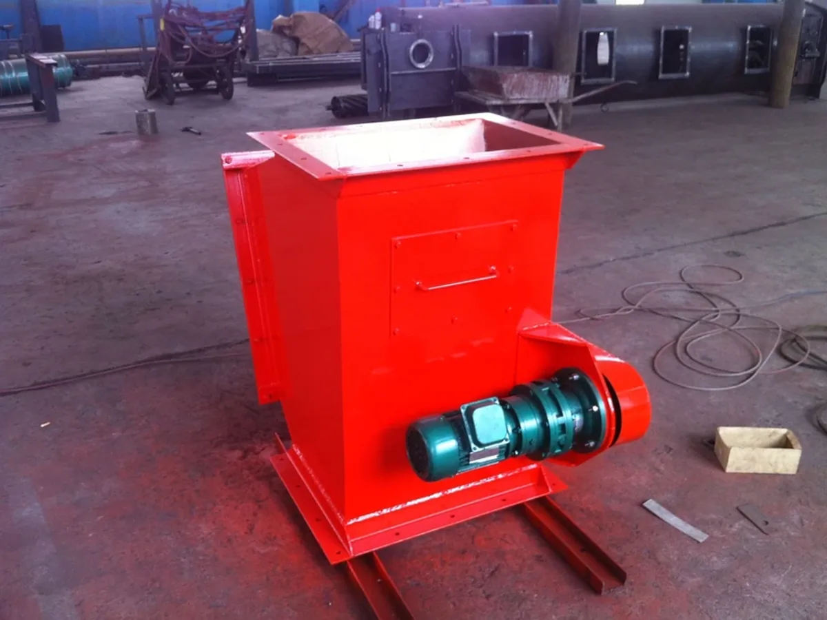
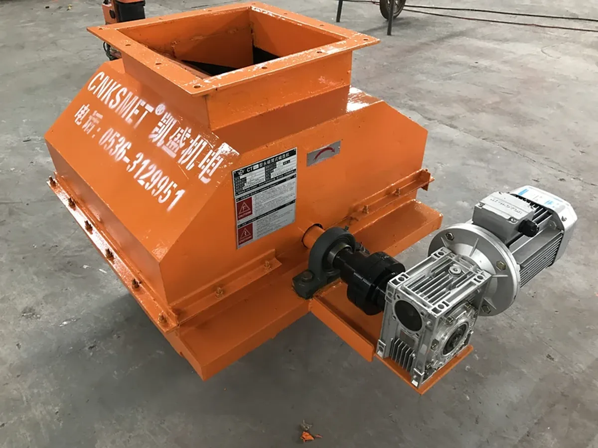
RCYG is used where dry powder or small granules move through a pipeline and captured iron needs to be discharged continuously. The RCYG series includes seven models from RCYG-100 to RCYG-1000, all with continuous automatic iron removal. The current model table lists a 380 V drive supply, with motor power increasing by model.
RCYG driven self-cleaning pipeline configuration.
| RCYG model | Listed capacity (t/h) | Cleaning | Listed ferrous particle size (≤ mm) | Motor power (kW) | Power supply (V) | Equipment weight (kg) |
|---|---|---|---|---|---|---|
| RCYG-100 | 80–120 | Continuous automatic | 30 | 0.37 | 380 | 320 |
| RCYG-150 | 130–160 | Continuous automatic | 50 | 0.37 | 380 | 380 |
| RCYG-200 | 180–220 | Continuous automatic | 80 | 0.55 | 380 | 560 |
| RCYG-400 | 350–450 | Continuous automatic | 100 | 1.1 | 380 | 1100 |
| RCYG-600 | 550–650 | Continuous automatic | 120 | 1.5 | 380 | 1500 |
| RCYG-800 | 720–880 | Continuous automatic | 150 | 2.2 | 380 | 1800 |
| RCYG-1000 | 900–1100 | Continuous automatic | 200 | 3.0 | 380 | 2200 |
The RCYG values above are current Corvelan series data. “Ferrous particle size” is a model-selection field for iron-removal particle size; it is not a separation-efficiency guarantee. Final selection still needs the actual material, contaminant, feed condition and installation point.
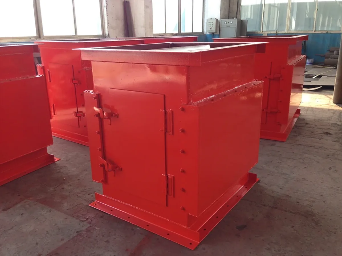
RCYA permanent-magnetic pipeline separator configuration.
The RCYA1 / RCYA2 series use permanent magnets and manual access for removing captured iron. RCYA1 is listed for lump and granular material at an installation angle of 40°–50°. RCYA2 is listed for powder at 55°–75°. The two series share the same model capacities and dimensional table in the current Corvelan data.
| Series | Material route | Listed installation angle | Cleaning / drive route |
|---|---|---|---|
| RCYA1 | Lump and granular material | 40°–50° to ground | Permanent magnet; manual access / cleaning |
| RCYA2 | Powder | 55°–75° to ground | Permanent magnet; manual access / cleaning |
| RCYA model | Listed capacity (≤ t/h) | Pipeline body L×W×H (mm) | Permanent magnet L×W×H (mm) | Flange opening L×W (mm) | Weight (kg) |
|---|---|---|---|---|---|
| RCYA1/2-15 | 15 | 800×520×140 | 400×500×200 | 620×240 | 260 |
| RCYA1/2-30 | 30 | 900×620×170 | 500×600×200 | 720×270 | 320 |
| RCYA1/2-50 | 50 | 1000×670×190 | 600×650×200 | 770×290 | 500 |
| RCYA1/2-80 | 80 | 1100×720×200 | 600×700×230 | 820×300 | 850 |
| RCYA1/2-100 | 100 | 1200×820×220 | 600×800×230 | 920×320 | 980 |
| RCYA1/2-150 | 150 | 1300×1020×240 | 800×1000×230 | 1120×350 | 1150 |
| RCYA1/2-200 | 200 | 1400×1220×280 | 800×1200×230 | 1320×380 | 1350 |
| RCYA1/2-300 | 300 | 1600×1420×310 | 1000×1400×230 | 1520×400 | 1580 |
The RCYA dimensional and capacity values shown here are current Corvelan series data. Use them as series-selection data, then confirm the final project interface and actual material condition before manufacture.
Corvelan designs this pipeline separator family for dry bulk material moving through an enclosed gravity-flow point. The current range covers powder, granules and lump / granular feed routes, depending on series. Typical application industries in the product data include cement, chemical, glass, ceramics, gypsum, building materials and food processing. Food-contact, hygiene and other compliance requirements still need to be confirmed for the actual project.
We only state product-contact material, hygiene status, pressure rating, hazardous-area status or other compliance details when they are defined and supported for the actual project.
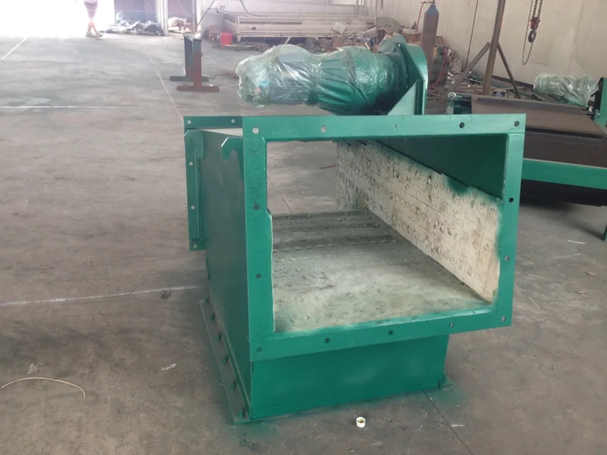
Flow-opening reference for reviewing clear passage, material presentation and line interfaces.
We place a pipeline magnetic separator at an enclosed gravity-flow transfer point where unwanted iron can be captured and removed safely. Common positions include:
Use magnetic separation upstream when tramp iron could damage or interfere with the next machine.
Remove unwanted iron before material enters the next mixing or blending step.
Add an in-line magnetic separation point where dry bulk material passes through a controlled chute or spout before discharge.
Install the separator in an enclosed chute or transfer line where the material path, opening and cleaning access can be clearly defined.
Use this table as a first fit check. Final selection still depends on the real material, line layout and the iron you need to remove.
| Process condition | Starting fit | Why | What we check next |
|---|---|---|---|
| Dry, free-flowing powder | Suitable starting point | Material can move through the magnetic area with limited build-up. | Particle size, feed depth, throughput and cleaning access. |
| Dry granules or pellets | Suitable starting point | Gravity flow can bring the product close to the magnetic capture area. | Largest pieces, clear opening, flow behavior and target metal. |
| Enclosed gravity chute or spout | Suitable starting point | The separator can be placed directly in the material path. | Inlet/outlet geometry, available height and service clearance. |
| High or frequent iron build-up | Review cleaning method | More captured metal can increase cleaning frequency and downtime. | How often the line can stop and whether driven/self-cleaning is needed. |
| Sticky, damp or cohesive material | Review flow path | Material may bridge, cake or build up inside the housing. | Clear opening, internal path and whether the product can stay close to the magnet. |
| Pressure pneumatic conveying | Use another pipeline design | Pressure, air speed and sealing change the equipment requirements. | Pressure, sealing, velocity, connection and pneumatic-line requirements. |
| Liquid or slurry | Use a wet-line magnetic separator | Liquid flow needs a different internal design and cleaning route. | Flow rate, viscosity, pressure, product-contact and cleaning requirements. |
| Sanitary or validated hygienic process | Dedicated project review | Cleanability, finish and documented compliance may become part of the design. | Product-contact construction, finish, cleaning method and required evidence. |
The separator creates a magnetic capture area inside the material path. We shape the inlet and internal passage so unwanted iron can pass close enough to the magnet. We also plan the cleaning route so the bulk material can keep moving through the line.
We size the inlet, outlet and clear passage around the material and required flow rate. Feed must also spread well because a deep or bridged layer can keep iron too far from the magnet.
The internal magnetic layout brings iron and steel close to the active magnetic field. The metal can then be held or moved away from the clean material path. This close-capture area is the magnetic working zone.
We choose the cleaning method from the amount of iron the separator may collect, how often the line can stop and the available service space. The final setup may use manual cleaning or a driven/self-cleaning method.
Corvelan looks at the iron you need to remove and the way your material moves through the separator. We use all six points together instead of choosing a separator from one magnetic number.
You tell us: the metal type, size and shape, and whether it is loose or mixed deep inside the material.
What it changes: the magnetic arrangement and how the material needs to pass the capture area.
You tell us: feed depth, material layer and where the contamination sits in the flow.
What it changes: the working distance and the magnetic condition needed at the real capture point.
You tell us: whether the product is free-flowing, damp, sticky, caking or unevenly fed.
What it changes: the clear opening, internal flow path and risk of bridging or build-up.
You tell us: normal and peak throughput, plus bulk density if known.
What it changes: the clear opening, feed depth and the amount of material passing the magnetic area at one time.
You tell us: whether iron appears only from time to time or builds up often. Engineers often call this ferrous loading.
What it changes: cleaning frequency and whether manual or driven/self-cleaning is the better route.
You tell us: line size, available height, opening direction and nearby equipment.
What it changes: inlet/outlet layout, service access, metal discharge and how the separator fits the line.
Send your material flow, expected amount of iron and installation drawing. We will compare manual and driven/self-cleaning routes before quotation.
Magnetic strength is only part of the job. The separator also needs to keep the material moving and present the product close enough to the magnetic area for iron to be captured.
Powder or granules can form an arch over a narrow opening and stop moving freely. We check the clear opening and internal path when bridging is possible.
Damp, sticky or fine material can collect on internal surfaces. We review the flow path, access and cleaning method when build-up is likely.
A deep layer can place some iron farther from the magnet. We check feed depth, throughput and the way material is spread through the capture area.
Gauss is a magnetic flux-density reading at a specific measurement point. It does not by itself tell you how much iron will be removed from a moving layer of powder or granules.
The useful magnetic condition at the contamination depends on working distance, material depth, particle position, metal size and magnetic response. Material flow and cleaning condition also affect how consistently the separator can work.
Corvelan builds the final separator around your material, expected iron load, line connection, available space and cleaning method. Before the project drawing is finished, we define how it connects, how much clear flow area is needed, how the magnetic capture area is arranged, how collected metal is removed and how the unit can be reached for service.
| Selection point | RCYA1 / RCYA2 permanent route | RCYG continuous automatic route |
|---|---|---|
| Cleaning method | Manual access / cleaning of captured iron. | Continuous automatic iron removal with driven cleaning mechanism. |
| Material route | RCYA1: lump / granular; RCYA2: powder. | Powder and small granular material. |
| Installation / power | RCYA1: 40°–50°; RCYA2: 55°–75°. Permanent-magnet route with no cleaning motor listed. | 380 V drive; listed motor power 0.37–3.0 kW by model. |
| When to review first | Use when manual access is practical and the listed installation angle fits the process. | Use when frequent iron discharge or reduced cleaning interruption is important. |
| What we need to choose | What affects it | What Corvelan sets |
|---|---|---|
| Inlet / outlet layout | Existing line size, flow direction and available height. | Connection type, orientation and project dimensions for the drawing. |
| Clear opening and internal passage | Material size, flow behavior, throughput and risk of bridging. | A clear material passage matched to the real separation point. |
| Magnetic layout | Type and size of metal, working distance and how material passes the magnet. | The magnetic capture-area layout and the project check used to confirm it. |
| Cleaning / metal-discharge method | Expected iron load, allowed downtime and cleaning access. | Manual or driven/self-cleaning route, plus how removed metal is collected. |
| Drive, guarding and controls | Selected cleaning method and site connection needs. | Driven parts, guarding and required control connections where the project uses them. |
| Construction / finish requirements | Material contact, wear, environment and required documents. | The project construction and finish after these needs are supplied and verified. |
These separators can all remove unwanted iron from dry bulk material, but they fit different parts of a process. We first look at how the material moves and how the magnet can be cleaned, not just the equipment name.
| Equipment | Works well when | Main thing to check |
|---|---|---|
| Pipeline Magnetic Separator | Material moves through an enclosed gravity chute, spout or transfer line. | Can the separator fit the line, keep a clear material path and leave enough room for cleaning and metal discharge? |
| Drawer Magnet | Free-flowing powder or granules pass through a housing with magnetic tubes arranged in removable drawers. | Is there enough room to pull the drawer out, and can the product pass around the tubes without bridging? |
| Magnetic Grate | Powder or granules can pass directly over or around magnetic tubes in a hopper, chute or gravity line. | Can the material make close contact with the tubes, and can the grate be reached for cleaning? |
| Plate Magnet | Material can flow past a magnetic plate mounted in or over a chute without blocking the product path. | Is the plate close enough to the unwanted iron, and can it be reached for cleaning? |
You do not need to know every technical value before contacting us. Start with the process information you already have. Corvelan uses it to define the mechanical and magnetic details needed for the project drawing and quotation.
| Input | What to provide | Why it matters |
|---|---|---|
| Material | Powder, granules, pellets or other dry bulk material; include flow behavior if known. | Material behavior affects the clear passage, feed presentation and cleaning needs. |
| Particle size | Typical range and largest expected pieces. | Large pieces and fines can require different flow clearances and magnetic presentation. |
| Throughput | Normal and peak flow rate. | Throughput must be reviewed with bulk density, feed depth and the clear opening. |
| Metal to remove | Tramp iron, steel fragments, fine iron or another magnetic target; include size if known. | The target metal helps define working distance and magnetic layout. |
| Line information | Chute / pipe opening, flow direction, available height, drawing or clear photos. | This defines how the separator must connect to the existing line. |
| Cleaning need | Expected iron build-up, acceptable stop time and preferred cleaning method if known. | This helps choose manual or driven/self-cleaning arrangements. |
| Operating conditions | Temperature, pressure, dust, hygiene, corrosion or other site requirements when relevant. | These conditions can change construction, sealing, finish and documentation needs. |
| Project item | What we define | Why it matters | How it is confirmed |
|---|---|---|---|
| Inlet / outlet | Connection geometry, orientation and project dimensions. | Lets the separator fit the existing line without forcing an improvised connection. | Project drawing. |
| Flow passage | Housing shape, clear opening and internal material path. | Helps the product move through the separator without unnecessary restriction or excessive feed depth. | Drawing plus application review. |
| Magnetic arrangement | Capture-area layout around the target metal, material path and working distance. | Places the magnetic field where the contamination actually travels. | Project specification and defined magnetic check when required. |
| Cleaning / metal discharge | Manual or driven/self-cleaning method and how removed metal leaves the unit. | Controls cleaning frequency, downtime and how collected iron is handled. | Drawing and functional check where moving parts are included. |
| Service access | Space needed to open, clean, inspect and maintain the separator. | Prevents an installation that works on paper but cannot be cleaned or serviced safely. | Installation drawing. |
| Construction / finish | Project-specific construction after material-contact, wear, hygiene and environment needs are supplied. | Matches the equipment to the real material-contact and site conditions. | Approved project specification. |
| Final checks | Dimensional, magnetic, functional or material checks that answer the agreed project question. | Makes the acceptance method clear before the equipment is judged. | Defined inspection / test method. |
Before we release the final drawing, Corvelan checks how the separator connects to your line. We also check flow direction, support, clear opening, cleaning space and where removed metal will go. The goal is a separator that fits the line, brings material close to the magnetic capture area and stays practical to inspect and clean.
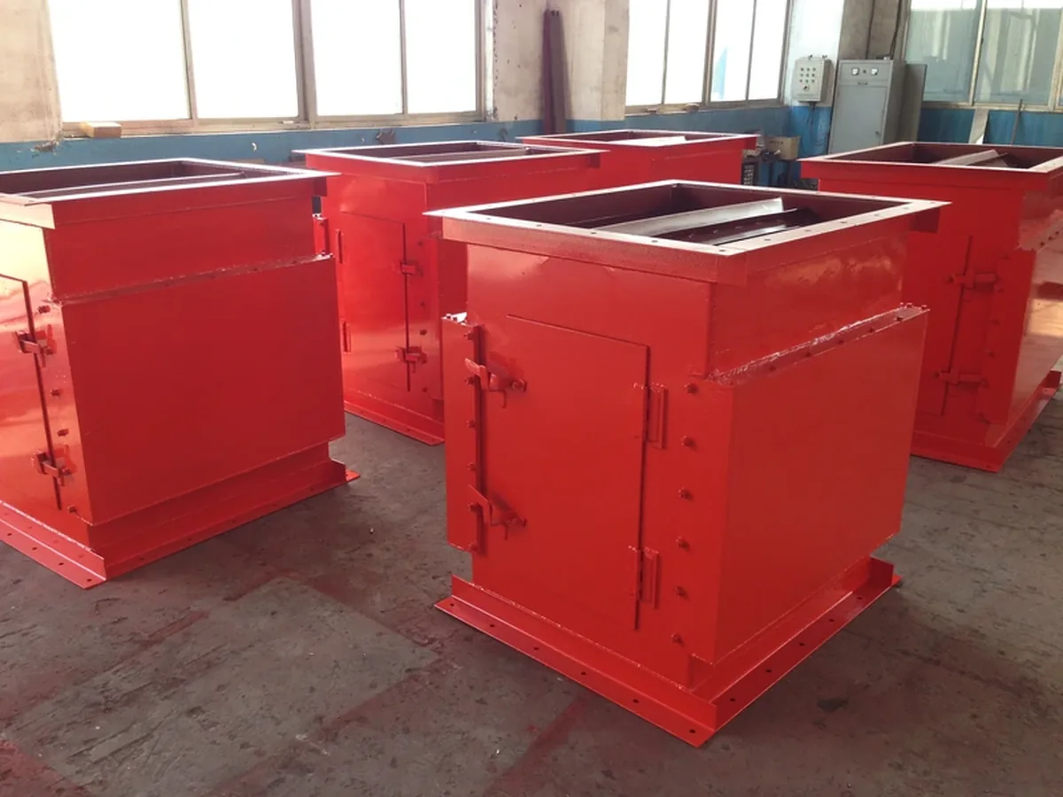
Pipeline separator family configurations for line integration. Installation dimensions come from the approved project drawing.
We define the inlet from the real upstream opening. Round, square or rectangular geometry depends on the line that the separator must join.
The outlet is matched to the downstream chute, hopper or process connection so material can leave the separator cleanly.
Flange or other connection details are taken from the project drawing instead of assumed from a generic catalog size.
We confirm whether the material falls vertically or at an angle because the direction affects material presentation and available space.
We confirm which side can be opened for cleaning, inspection and removal of captured metal.
The separator must fit between the equipment above and below it while keeping enough room for safe cleaning and maintenance.
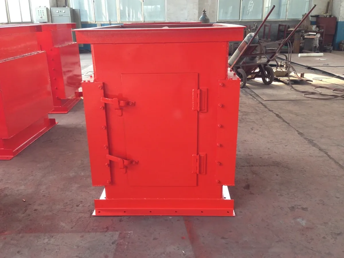
Access arrangement for planning cleaning, inspection and service clearance.
The current Corvelan range gives two clear cleaning routes. RCYA1 / RCYA2 use permanent magnets with manual access for removing captured iron. RCYG uses a geared-motor cleaning mechanism for continuous automatic iron removal. We choose between these routes from material type, expected iron loading, allowed downtime, installation angle and available service space.
Before final approval, we agree on what each check needs to prove. Engineers may call this the acceptance check. The drawing confirms fit. A defined magnetic measurement checks the magnetic condition. A function check confirms the cleaning or drive system. A material trial is used when the result depends on the actual product.
Confirm the inlet, outlet, mounting, access and maintenance space against the approved project drawing.
If magnetic flux density is part of the check, measure it at a defined point and distance with a defined probe direction and method.
For driven equipment, check the direction, movement, cleaning or discharge action, controls and relevant safety functions.
If the result depends on the real product, use material that closely represents the actual process. Record the test conditions at the same time.
A sample or factory test shows what happened under the recorded test conditions. It does not guarantee the same result under every production condition.
We confirm installation dimensions in the drawing, specified magnetic measurements during inspection, and material performance through testing when required. We use the same Drawings, Inspection and Material Testing structure commonly expected for industrial magnetic separation projects, while the exact evidence package is confirmed for the Corvelan project scope.
Supports inlet, outlet, mounting, clear opening, service space and other agreed dimensions.
Supports a defined magnetic condition only when the measurement point, distance, probe direction and method are recorded.
Supports movement, cleaning, discharge or controls where those functions are part of the selected separator.
Supports a separation result only for the recorded sample, separator setup and operating conditions used in the test.
Corvelan matches the magnetic design to your material, the real line layout and the way you want the finished separator checked. We do not choose a separator from one Gauss number alone.
We size the separator around your material, the unwanted metal, required throughput and the actual separation point.
You receive: a project basis tied to the real material and contamination target.
We define the inlet and outlet, clear opening, maintenance space and cleaning or metal-discharge method around your line layout.
You receive: connection and installation details for the project drawing.
We confirm whether the project needs a drawing check, magnetic measurement, function check or material test.
You receive: a clear inspection scope instead of one vague performance claim.
We turn the process information you send into the details needed for the project drawing and quotation.
You receive: a defined technical basis for the next commercial step.
These names can overlap in the market, but they do not always describe the same machine. A pipeline magnet, pipe magnetic separator or inline magnetic separator may be used for dry bulk, pneumatic, liquid or slurry service depending on the supplier and the process.
On this page, Corvelan uses pipeline magnetic separator for a dry-bulk, gravity-flow separator installed in an enclosed chute, spout or transfer line. Liquid magnetic traps, slurry separators and pressure pneumatic separators need different flow, sealing, pressure and cleaning reviews.
Choose the equipment from the material and process condition first, not from the product name alone.
A pipeline magnetic separator removes unwanted iron and steel from dry material as it moves through an enclosed chute, spout or gravity transfer line. This unwanted metal is called ferrous contamination, and the active capture area is called the magnetic working zone.
This page covers dry powders, granules and small bulk solids that move through an enclosed gravity-fed or chute-style transfer point. Corvelan checks how the material flows, particle size, moisture, bulk density, required throughput and clear opening before we define the final design.
Yes. Send us your line dimensions, drawing or clear photos. We use the real line size, flow direction, available height and maintenance space to match the inlet, outlet and layout before quotation.
Corvelan offers both routes in the current series. RCYA1 / RCYA2 use permanent magnets with manual access for cleaning. RCYG uses continuous automatic iron removal with a driven cleaning mechanism. We choose the route from material type, iron loading, allowed downtime, installation angle and service space.
No. Gauss describes magnetic flux density at a defined measurement point. The actual separation result also depends on working distance, feed depth and material flow. Metal size, magnetic response, field change with distance and the removal method also matter.
A gravity-flow separator handles material that falls through the housing by gravity. A pneumatic pipeline separator works inside a pressure or vacuum conveying line, so air speed, pressure, sealing and connection design become additional engineering requirements. Liquid and slurry lines need a separate wet-line magnetic separator route.
Start with the material, the metal you need to remove, normal and peak throughput, and the installation condition. If available, also send particle size, moisture or bulk density, and the expected amount of iron. Inlet and outlet dimensions, available space, temperature, cleaning preference, and a line drawing or photo are also useful.
Not always. The names can overlap, but many magnetic traps are made for liquids or pressure lines. This page covers a dry-bulk gravity-flow separator. The material and process condition should be checked before the equipment name is used to choose a design.
No. Start with the material, metal to remove, throughput and line conditions. If a Gauss value is later used as a project check, Corvelan will also need the measurement point, working distance and test method so the value can be understood and repeated.

You do not need a finished specification before contacting us. We use the application data to narrow the separator type first, then turn the confirmed information into a buildable project scope.
We check the material, unwanted metal, throughput and installation conditions.
We confirm whether this dry-bulk pipeline separator is the right starting design or whether another separator type fits better.
We confirm the remaining dimensions, flow opening, cleaning method, service access and project-check requirements.
The confirmed information becomes the basis for the project drawing and quotation.
You do not need a complete specification to contact us. Start with four items. Corvelan uses them to choose the right separator type and confirm any missing details needed for the drawing and quotation.
Start with what you know: if some values are still unknown, send the material and line information you already have. We will identify the missing points that matter before the drawing and quotation are finalized.
Send the material, the metal you need to remove, throughput and installation condition you already have. We will use that information to choose the right separator setup and confirm what is still needed before drawing and quotation.