
Large steel pieces
For crusher or equipment protection, define bucket teeth, steel plates, tools or broken machine parts that could cause the highest damage. The reject path must pass the largest expected piece.
Find equipment by installation point and separation task.
All magnetic separators →Start with the material or production line you need to protect.
All applications →Compare technologies, check parameters and prepare your RFQ.
All guides →See the factory, quality checks and answers before you request a quotation.
Continuous Conveyor Tramp-Iron Removal
Use this separator when ferrous tramp metal appears frequently on a conveyor, manual cleaning would interrupt production, and automatic iron discharge is required. Corvelan selects the final configuration from the target iron, real working distance, burden depth, belt speed, conveyor layout, discharge path and site conditions.
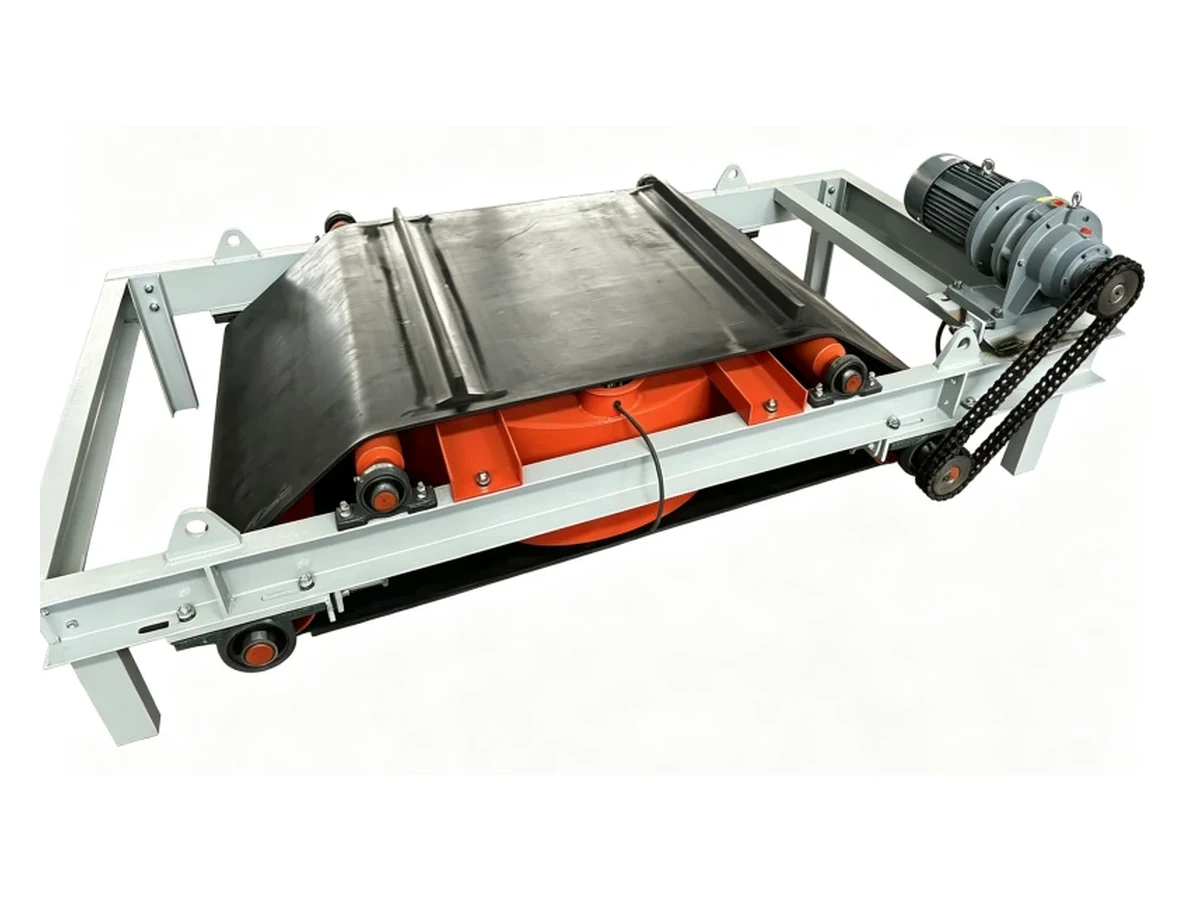
Corvelan self-cooled self-unloading suspended electromagnetic separator. Final size, electrical scope and mounting details follow the approved project documents.
Page Guide
Start with the process fit, then lock the configuration, installation, electrical scope, acceptance method and delivery package before manufacture.
Quick Decision
Choose a self-cooled self-unloading suspended electromagnetic separator when iron or steel appears often, the conveyor should keep running, and the required magnetic reach is better handled with an electromagnet. Use a simpler or different separator when the process does not match those conditions.
| Your operating condition | Corvelan starting choice | Do not choose | Lock before order |
|---|---|---|---|
| Iron or steel appears frequently and production should continue without routine manual cleaning. | Self-unloading suspended electromagnet. | Manual-clean when regular cleaning stops are unacceptable. | Iron frequency, target iron, discharge path and cleaning-belt direction. |
| Iron appears only occasionally and a safe planned stop is acceptable. | Manual-clean suspended magnet. | Do not add a self-unloading belt only for the sake of automation. | Safe cleaning access and expected iron loading. |
| The target is difficult because it is small, buried deep, far from the magnet or moving fast. | Electromagnetic separator sized from the hardest target position. | Do not select from conveyor width or surface Gauss alone. | Target piece, bottom position, burden depth, belt speed and working distance. |
| The magnetic reach is modest and excitation power is unnecessary. | Compare a permanent suspended magnet. | Do not use an electromagnet automatically when a permanent unit can meet the real target condition. | Target iron and real working distance. |
| Captured iron can leave safely to the side of a straight conveyor section. | Cross-belt layout. | Do not use inline by habit. | Discharge side, chute/bin, service space and surrounding steel. |
| The best magnetic position is near the head pulley and side discharge is blocked. | Inline layout. | Do not force a cross-belt unit into restricted side space. | Head-pulley geometry, material trajectory and longitudinal discharge path. |
| The material is damp or wet but still moves as normal conveyor-fed bulk material. | Suspended separator remains suitable. | Do not switch to a slurry separator only because the material surface is wet. | Buildup, carryback, corrosion, electrical protection and reject-area drainage. |
| The process is a real slurry or liquid circuit. | Use a wet magnetic separation system. | This over-conveyor separator as the main magnetic stage. | Slurry solids, particle size, target magnetic material and process flow. |
| The main target is aluminum, copper or another non-ferrous metal. | Use a non-ferrous separation system. | This suspended electromagnet as the main separator. | Metal type, size, feed condition and downstream requirement. |
| The goal is very fine final-product cleanup. | Use this unit as a coarse magnetic stage only when it fits the process; add a finer magnetic stage if required. | Do not treat successful tramp-iron removal as a guarantee of fine cleanup. | Smallest important contaminant and required final product condition. |
Product Overview
It is an over-conveyor electromagnetic separator that lifts ferrous tramp metal from moving bulk material and uses a moving cleaning belt to carry the captured metal out of the magnetic field for automatic discharge.
This equipment is also commonly described as a self-cleaning suspended electromagnet, self-cleaning electromagnetic separator or electromagnetic overband separator. Corvelan uses the project operating condition—not the name alone—to determine the final configuration.
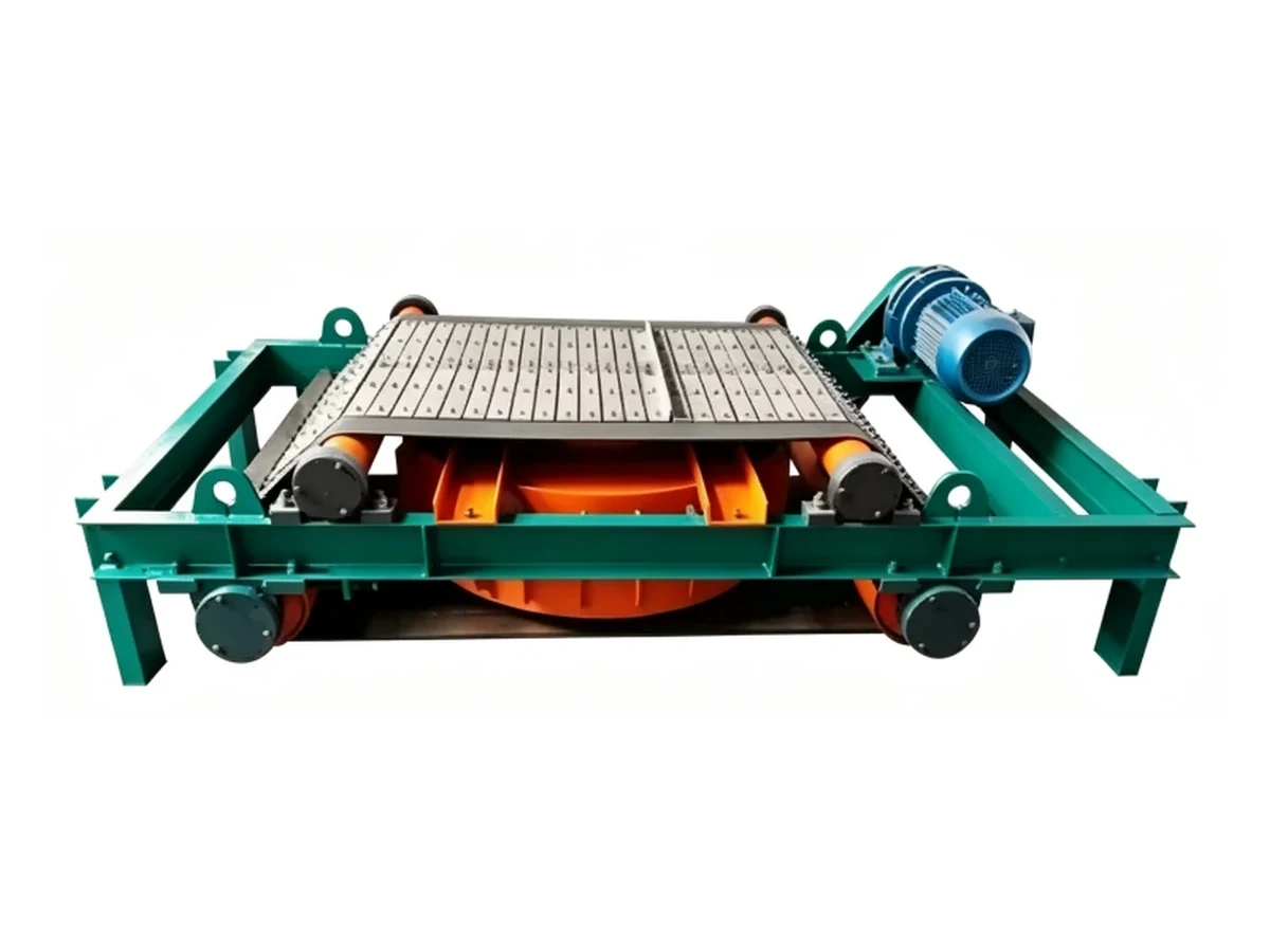
Self-unloading belt, rollers and drive arrangement on a Corvelan configuration.
Target Iron
“Remove iron” is not a complete selection requirement. We define the separator from the iron piece that is hardest to capture and the largest piece that must pass through the discharge path.
For crusher or equipment protection, define bucket teeth, steel plates, tools or broken machine parts that could cause the highest damage. The reject path must pass the largest expected piece.
Long pieces can bridge between the cleaning belt, frame and chute. Use open discharge geometry instead of sizing the reject path from mass alone.
Small pieces become difficult when they are buried at the bottom of a deep burden or move through the magnetic zone at high speed. Select from the hardest position.
If the final product must be cleaned of much smaller ferrous contamination, define that contaminant separately and use a downstream magnetic stage when required.
Choose for the most dangerous steel piece and the hardest realistic position where it can appear before the protected crusher, mill, screen or conveyor transfer.
Choose from the smallest contamination that still matters to the final product. A tramp-iron separator selected for crusher protection is not automatically a fine-cleaning separator.
Project Specification
A model number or conveyor width alone is not enough. Corvelan locks the project-specific selection basis, mechanical arrangement, electrical requirement and agreed checks in the quotation, approved drawing or technical specification.
| Specification item | What we lock | Decision rule |
|---|---|---|
| Conveyor belt width | The actual belt width and loaded profile. | Used for coverage and mechanical fit, not as the only model-selection input. |
| Target iron | Smallest important target, largest expected piece, typical shape and frequency. | Select magnetic reach from the hardest target; select discharge clearance from the largest target. |
| Working distance | Distance from the magnet face to the hardest required iron position. | Use the real target distance, not only magnet-to-belt clearance. |
| Burden depth | Normal and maximum material depth. | Use the maximum operating burden for the difficult-capture condition. |
| Belt speed | Normal and maximum conveyor speed. | Use maximum speed when capture performance must still be maintained at that condition. |
| Installation orientation | Cross-belt or inline, discharge side and magnet position. | Choose from conveyor geometry and the safest reject path. |
| Mechanical envelope | Overall size, suspension points, drive position and service clearance. | Freeze these in the approved project drawing. |
| Self-unloading arrangement | Cleaning-belt direction, drive position, rollers and reject direction. | Match the actual chute/bin location and maintenance access. |
| Cooling arrangement | Cooling hardware and required airflow/service condition for the selected unit. | Match ambient temperature, running duty, dust and enclosure condition. |
| Electrical requirement | Site input, excitation system requirement, drive/fan supply and required controls. | Lock included and site-supplied items before production. |
| Acceptance method | Dimensional, functional, electrical and any agreed magnetic/capture check. | Write the pass condition before manufacture when a result must be accepted at shipment. |
Selection Rules
Start with the hardest iron to capture, then work outward to distance, burden, speed, discharge and environment. These rules prevent a separator from being chosen from an easy top-layer target or a catalog magnetic number.
Define the smallest or most difficult piece that still matters, plus the largest piece that must pass through the reject path.
Measure from the magnet face to the hardest required iron position inside the material.
Use the deepest operating material layer when bottom iron must still be captured.
Use the highest required operating speed when the separator must maintain capture under that condition.
| Condition | Corvelan action | Do not do this |
|---|---|---|
| High speed + deep burden + small iron | Treat it as a difficult-capture application and define a project-specific capture condition. | Do not release the order from conveyor width or surface Gauss alone. |
| Large air gap caused by surrounding steel | Change the installation or support geometry first when possible, then select the magnet from the corrected working position. | Do not accept unnecessary magnetic distance just because the existing steelwork is convenient. |
| Deep material but low magnet-to-belt clearance | Use magnet face to bottom target distance as the selection distance. | Do not treat a small magnet-to-belt gap as proof that bottom iron is close to the magnet. |
| Very frequent or bulky tramp iron | Use self-unloading and design the reject route from the expected piece size and iron loading. | Do not size the chute from belt width alone. |
| Final-product fine cleanup | Define the smallest critical contaminant and decide whether a second magnetic stage is required. | Do not use a coarse tramp-iron success criterion as a fine-cleaning guarantee. |
Cross-Belt vs Inline
Use cross-belt when captured iron can leave safely to the side; use inline when the best magnetic position and available reject path follow the conveyor direction.
| Your layout | Use | Before we approve it |
|---|---|---|
| Straight conveyor section with clear left or right reject space. | Cross-belt | Lock discharge side, chute/bin position, support structure and service access. |
| Best magnetic position is near the head pulley or transfer and side clearance is restricted. | Inline | Lock head-pulley geometry, material trajectory, reject path and maintenance space. |
| No safe reject space beside the conveyor. | Do not default to cross-belt. | Check whether inline creates a safer iron-discharge route. |
| No usable space at the conveyor head or transfer end. | Do not default to inline. | Move to a cross-belt position or change surrounding steelwork. |
| Steel beams, chutes or platforms force the magnet too high. | Correct the structure first. | Do not lock a poor working distance before checking a better support position. |
Self-Cooled Configuration
Use the self-cooled arrangement as the starting configuration when the selected unit can receive the airflow and service clearance required by its cooling hardware under the real ambient and duty conditions. We do not treat cooling as a generic label; it is part of the project operating condition.
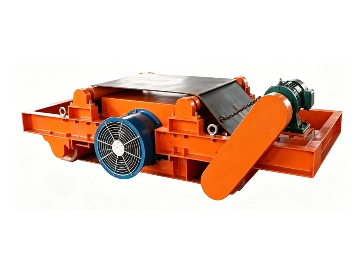
A Corvelan self-cooled configuration with visible external cooling hardware. Final cooling arrangement follows the selected unit and project operating condition.
Electrical & Controls
Lock the electromagnet excitation requirement, self-unloading drive supply, cooling supply and control boundary before manufacture. Do not leave rectifier, control cabinet, interlock or field-cable responsibility as a verbal assumption.
| Electrical item | Function | What the quotation / technical agreement must state |
|---|---|---|
| Electromagnet excitation | Powers the magnetic coil. | Required excitation arrangement and the site input needed for the selected project. |
| Excitation power / rectifier equipment | Provides the required electrical supply to the electromagnet. | State clearly whether it is included in the Corvelan supply or provided by the site. |
| Cleaning-belt drive | Runs the self-unloading belt. | Motor/drive supply data, direction and included control boundary. |
| Cooling hardware | Supports heat removal for the selected self-cooled configuration. | Supply requirement, operating condition and access/airflow requirement. |
| Local controls | Local start/stop or indication where included. | List the actual functions included in the order. |
| Conveyor interlock | Coordinates separator operation with the conveyor or plant sequence. | Required input/output signals and which side supplies the field connection. |
| Isolation and field cabling | Supports safe electrical installation and maintenance. | Define isolator, cable and termination responsibility before shipment. |
Engineering Selection Examples
Use these engineering examples to compare different conveyor conditions. Final selection is based on your actual material, target iron, working distance, burden depth, belt speed and installation layout.
Situation: 1,200 mm conveyor, 1.6 m/s belt speed, up to 220 mm burden, with bucket teeth, steel plate and broken tools appearing regularly.
Choose: a self-cooled self-unloading suspended electromagnetic separator. Use cross-belt when there is enough side space for the reject chute and collection bin.
Do not choose: manual-clean when routine cleaning stops are not acceptable.
Situation: 800 mm conveyor, 0.8 m/s, about 100 mm burden, with only occasional bolts and small steel parts.
Choose: a manual-clean suspended magnet.
Do not choose: self-unloading only because it is more automatic.
Situation: 1,000 mm conveyor, magnet over a straight belt section, with 1.5 m of clear space on the right for a chute and bin.
Choose: cross-belt with right-side discharge.
Do not choose: inline when the conveyor-end space is restricted and the side reject route is already clear.
Situation: 1,200 mm conveyor, best magnetic position near the head pulley, restricted side clearance and useful space in the conveyor direction.
Choose: inline.
Do not choose: cross-belt when walkways or steelwork block the side reject zone.
Situation: 1,000 mm conveyor, 1.2 m/s, damp aggregate after washing, wet surface but no slurry flow.
Choose: a suspended electromagnetic separator remains suitable.
Do not choose: a slurry separator only because the material is wet.
Situation: particles are carried through a liquid circuit with no normal conveyor burden under an overband magnet.
Choose: a wet magnetic separation system designed for the slurry process.
Do not choose: this suspended overband separator as the main magnetic stage.
Situation: 1,400 mm conveyor, 2.8 m/s, up to 300 mm burden, with small steel bolts near the bottom.
Choose: an electromagnetic separator sized from the bottom target condition and require a project-specific capture test when that target is part of the purchase acceptance.
Do not choose: a catalog model from conveyor width or surface Gauss alone.
Situation: the process already protects the crusher, but the finished material still contains smaller ferrous contamination.
Choose: keep the suspended electromagnet as a coarse stage where appropriate and add a finer magnetic stage when the final cleanliness requirement demands it.
Do not choose: large-steel capture as the only acceptance rule for fine cleanup.
Installation & Service
Show the loaded conveyor profile, proposed magnet position, surrounding steel, suspension area, reject path and service space. We use that layout to prevent a separator from fitting the belt width but failing the real installation.
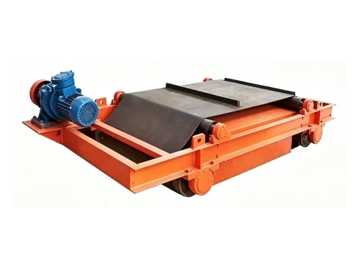
Visible frame, cleaning-belt and drive construction used to plan the mechanical envelope and service access.
Cleaning, Maintenance & Safety
Keep the self-unloading belt, rollers, drive, cooling path and reject zone free to operate. Stop and isolate the equipment before correcting tracking, trapped metal, abnormal vibration or blocked airflow.
Stop the unit and check roller alignment, belt tension, buildup and trapped metal. Do not continue running a belt that is rubbing the frame or drive area.
Check the reject opening, iron size/shape, cleaning-belt movement and chute/bin path. Increase the open path or change the reject layout when long or bulky pieces bridge the discharge area.
Remove dust or obstruction from the required airflow path and keep the cooling area reachable for regular cleaning.
Stop the equipment and inspect the drive, rollers, bearings, fasteners, belt and any trapped ferrous material before restart.
Pre-Shipment Acceptance
If you require a performance test, we agree on the test conditions and pass criteria before manufacturing. This prevents the shipment from reaching final inspection with both sides using different definitions of “pass.”
| Check | Test condition | What is recorded | Pass point |
|---|---|---|---|
| Dimensions / mounting | Approved project drawing | Main dimensions, orientation and mounting arrangement | Matches the approved drawing revision. |
| Cleaning-belt direction | Powered functional run | Direction and reject side | Moves toward the agreed discharge side. |
| Belt tracking | Functional run | Running condition | Runs steadily without unacceptable side tracking. |
| Drive system | Powered functional run | Drive / roller operation | Operates correctly for the agreed check. |
| Cooling hardware | Selected configuration energized as agreed | Installed cooling arrangement and operation | Matches the approved configuration and operates during the agreed check. |
| Electrical scope | Against the order documents | Nameplate / supply / included controls | Matches the agreed electrical requirement. |
| Magnetic measurement, when specified | Defined energized condition, distance, points and instrument | Measurement values and positions | Meets the exact requirement written into the order. |
| Capture test, when specified | Defined test piece, position, working distance, speed and burden condition | Test condition and result | The agreed target is captured under the agreed condition. |
| Reject / discharge test, when specified | Defined target piece and discharge route | Discharge path/result | The captured target reaches the agreed reject area. |
| Final visual / nameplate | Final equipment | Visual condition and identification | No unresolved item against the agreed final inspection list. |
| Packing / shipment | Agreed supply scope | Packing list and shipment check | Shipment matches the agreed packing scope. |
Supply Scope
Use the quotation and technical agreement as the supply boundary. Do not assume a cabinet, support steel, reject chute, cable or installation service is included unless it is listed in the agreed scope.
| Item | How to treat it | What must be clear before order release |
|---|---|---|
| Electromagnetic separator main assembly | Core equipment scope | Selected project configuration and main mechanical arrangement. |
| Self-unloading belt, rollers and drive assembly | Core self-unloading equipment scope | Cleaning direction, drive arrangement and reject side. |
| Selected cooling hardware | Part of the selected self-cooled configuration | Exact arrangement shown in project documents. |
| Excitation power / rectifier equipment | Confirm in quotation | Included by Corvelan or supplied by site. |
| Local control cabinet / control components | Confirm in quotation | Functions, location and included signals. |
| Suspension hardware | Confirm in quotation | Which chains, turnbuckles, beams or connection items are included. |
| Structural support steel | Project-specific | Corvelan supply or site-fabricated structure. |
| Reject chute / collection bin | Project-specific | Included or site scope, plus the required opening for the largest target. |
| Field power cable / plant MCC connection | Define as site or quoted scope | Cable boundary, termination point and isolator responsibility. |
| Installation / commissioning service | Project-specific | Whether on-site service is included, optional or site-performed. |
| Project documents | List in the order | Approved drawing, technical specification, electrical information, manual and any agreed inspection/test record. |
Corvelan Project Control
We separate visual construction, project dimensions, functional checks and performance checks so each item is used for the decision it can actually support.
Use Corvelan product photos to review visible mechanical construction, self-unloading belt arrangement, rollers, drive position, guarding and visible cooling hardware.
Use the approved drawing to lock overall dimensions, orientation, mounting points, cleaning-belt direction, drive position and service clearance.
Use the functional check to confirm cleaning-belt direction, tracking, drive/roller operation, reject direction and the selected cooling hardware operation where applicable.
When the order includes a magnetic measurement or defined target capture requirement, the result applies to the exact condition written into that inspection requirement.
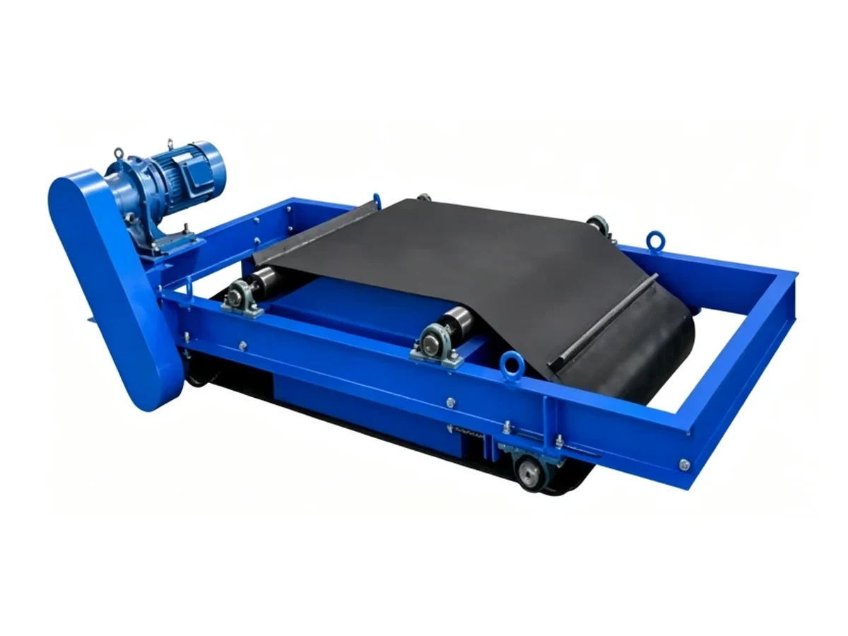
Corvelan product configuration showing an external frame and drive arrangement.
When you send a conveyor drawing and target condition, we can compare the mechanical arrangement and test requirements directly instead of relying on a generic product photograph.
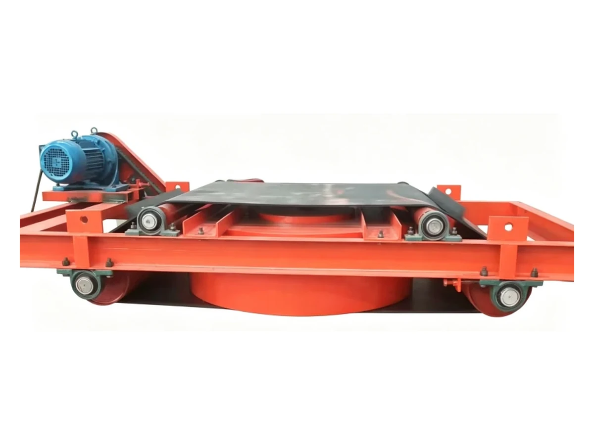
A Corvelan product variant showing that frame, drive and external arrangement can change with the selected project configuration.
Why Corvelan
We start from target iron, working distance, burden depth, speed, reject path and site conditions instead of selecting from belt width alone.
The approved project drawing controls orientation, major dimensions, mounting position, cleaning direction, reject side and service space.
If a magnetic value or target capture result matters to the purchase requirement, we write the condition and pass point before manufacture.
The quotation and technical agreement identify what Corvelan supplies, what is project-specific and what must be provided by the site.
FAQ
Choose self-unloading when iron appears often enough that manual cleaning would interrupt production or allow captured iron to build up too quickly. Choose manual-clean when iron loading is low and safe planned cleaning stops are practical.
Use cross-belt when the separator is over a normal conveyor section and captured iron can leave safely to the side. Use inline when the best magnetic position is near the head pulley or transfer and the reject path follows the conveyor direction. Lock reject space, surrounding steel and service access before finalizing.
Yes, when the material still behaves as conveyor-fed bulk material. Check buildup, carryback, corrosion, electrical protection and the reject zone. For a real slurry or liquid circuit, use a wet magnetic separation system instead.
No. A Gauss value applies to a specific measurement point. Select the separator from the target iron at the real working distance, burden depth and belt speed, and define the measurement position when magnetic data is part of the order.
State the test piece material, size, shape and mass; its position in the burden; belt speed; burden depth; working distance; and the exact pass condition. If discharge is part of acceptance, also define where the captured piece must be rejected.
Confirm the electromagnet excitation requirement, excitation power or rectifier scope, cleaning-belt drive supply, cooling supply, local controls, interlock signals, isolation and field-cable boundary.
Confirm the material, conveyor width and speed, maximum burden depth, target iron, working distance, cross-belt or inline layout, reject path, electrical requirement, ambient condition, service space, supply scope and agreed acceptance checks.
Start with four items: the conveyed material, the iron or steel you need to remove, the conveyor loading information you already have, and a conveyor drawing or clear installation photos. Add belt width, belt speed, burden depth, target iron size/frequency, available height, site power and acceptance requirement when available.
RFQ
You do not need a complete specification to start. Send the information that changes the separator choice, and Corvelan will identify what must be locked next.
We check whether this self-unloading suspended electromagnet is the right separator or whether the process needs another magnetic/non-ferrous separation method.
We choose cross-belt or inline from the magnetic position, surrounding steel and the safest reject path.
We identify the working distance, burden depth, speed, target iron, electrical, cooling and service information required for the quotation and drawing.
If magnetic measurement or target capture is part of the purchase requirement, we define the test condition and pass point before production.
Send the material, target iron, conveyor operating data and installation layout. Corvelan will review the separator type, magnetic working condition, cross-belt or inline arrangement, reject path and the project information required for quotation.